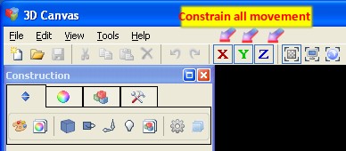
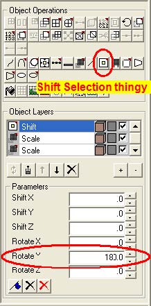
The Piper Tool won't create the elbow in the proper direction for this project so we have to spin our object around 180 degrees. Left-click on the object to select it (if it isn't already selected) then left-click on the Shift Selection icon (lower left of interface in Object Operations). Below that, under Object Layers, enter 180 in the Rotate Y text field box then hit ENTER. Make sure all the other text fields are zeroed.
We now have our object resized and shaped, and are ready to make the elbow we're going to use for our 3D chain link using the Piper Tool.
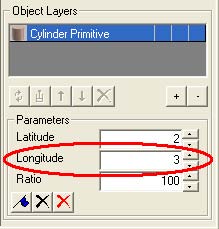
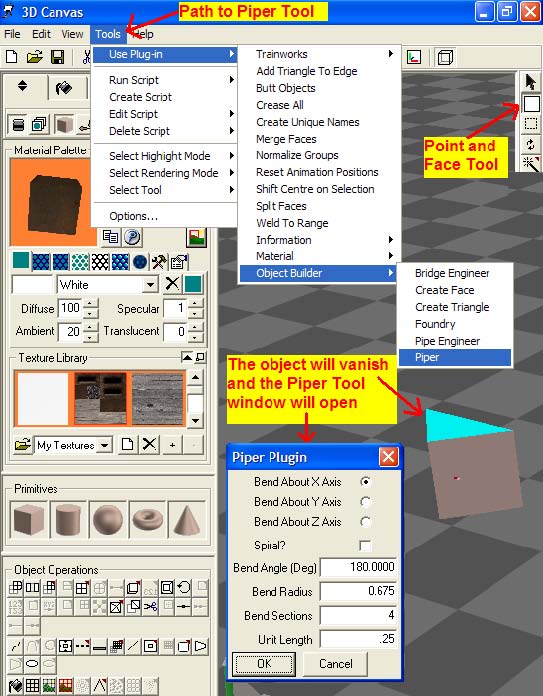
Left-click on the Point and Face Selection Tool (upper right corner, second button from the top) then left-click the top face to select it: it'll turn blue. Now open the Piper Tool and enter the values in the text fields as shown in the image below. Make sure the Bend About X Axis radio button is also checked in that window (this is another area that you can experiment with, using your own values). The next two images will explain this whole procedure because our object will vanish. I don't know why but, after you click OK or hit ENTER all is well again. The second image will show us our results:
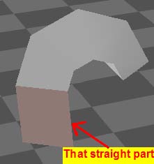
Voilà! We're on our way. Hopefully, your object looks similar to mine here. The hard part is over and all we need to do now is build our link. (The hard part is figuring out length, width, curvature and all the math that goes into creating an accurate model such as this or hand railings or whatever. In this case, I've done all that for you.)
Note that there are now two objects, one being the elbow - that's the one we want. Left-click on the Component Selection Tool upper right corner of the interface, with the big black arrow on it) then left-click on that straight part. Press DELETE. We're only going to need the elbow to make our 3D chain link.
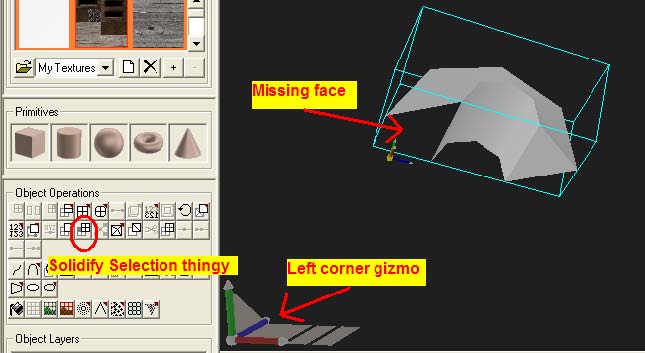
Use the left corner gizmo to roll the object over to look at the bottom. We're going to solidify our object because we need to 'fix' that missing face. Left-click on the elbow to select it (if it isn't already selected) then left-lick the Solidify Selection icon (lower left of interface in Object Operations). We now have a face we can extrude from: that's the next step.
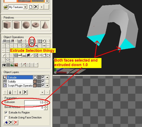
Ctrl-left-click on the other face to select it as well. While both faces are selected, left-click on the Extrude Selection and enter the following values in the text fields, then press ENTER.
There's only two more items to go, a little clean up, a quick texture, resize it to a more appropriate scale and we're done.
Jump up to the
Component Selection Tool (upper right corner of the interface with the big black arrow on it), left-click it to select our object again, left-click our object, then left-click on the
Shift Selection icon and enter the following vlaues in the text fields: remember that we used it above to flip it around; we now have to flip it over.
Rotate Z, enter 180 then press ENTER. Use the left corner gizmo to roll your model back to the upright position for better viewing of the next step. Left-click on the
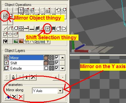
Mirror Object icon (you should know where all the icons are by now). Again, 3DC won't render our object properly so we have to flip it over.
If your model doesn't look like a chain link after this operation then you probably need to use the drop down menu and left-click on the Mirror Along tab, select Y axis in Parameters. Here's another image to help you out.
We're finally done with all the icon operations. It's now time to clean it up and throw a texture on it.
Return to top of page
Final Clean Up
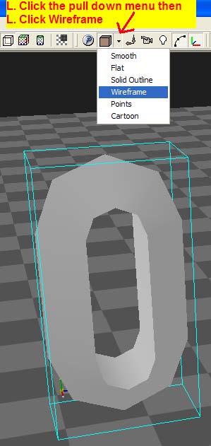
Let's view it in wire-frame mode. It'll be much easier to clean it up this way. Let's also take a look at the poly count as it stands now. The next two images should help you with all of that (the pull-down menu is just to the left of center at the top of the interface in the Main toolbar):
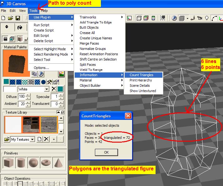
Looking at the wire-frame view we can see a few items that can be eliminated. Those six lines and six points on the straight sections can surely be trimmed off. Let's do it, then look at the poly count.
Jump to the Point and Face Selection Tool (upper right corner), left-click then hover your mouse pointer around one of the lines at its center. It'll turn yellow when you catch it. Freeze your mouse then right-click to open that window, left-click, Trim. We just want the line! This can be a tricky process so watch what you're doing. If you accidentally catch the whole face and trim that off, then you'll have to jump to the Top Tool Bar to hit the Undo button to try it again. To make matters worse, you won't know it until you go back into Smooth mode view. So, be careful trimming lines and points.
Go ahead and Trim off all six lines and all 6 points IN THAT ORDER then check the poly count. Again trim the lines first then the points (trust me!). Here are before and after shots, respectively.
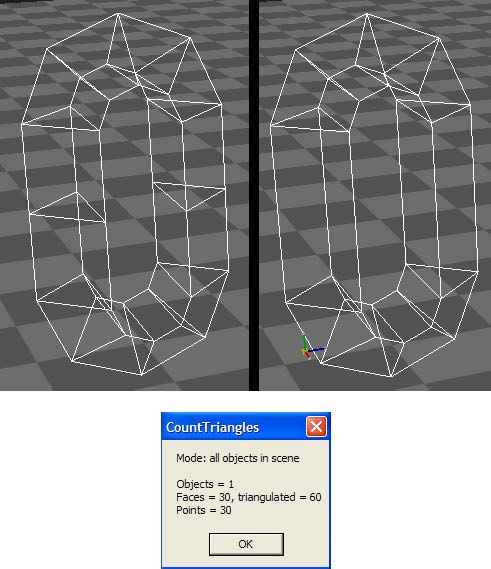
Poly count is now at 60: we've knocked off 12 polygons and 12 points. I don't think we can do any better then this and still have a good looking 3D chain link, in my opinion but you're welcome to try.
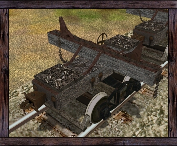
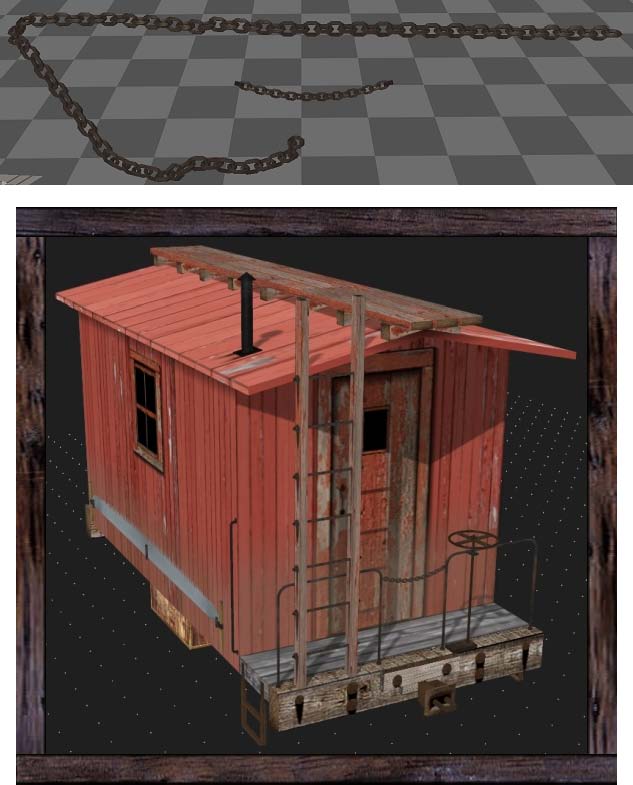
Go back to Smooth view and bucket fill a rusty texture on it. Now you're ready to assemble it to make yourself a length of chain but that's easy. Once you make two attached links, you can copy and paste to make 4 links then copy again to make 8 links, then again to make 16 then...
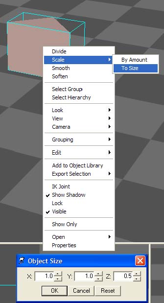
Got the idea? OK, good. Now scale it down to be proportionally accurate for the sim. At the beginning, I showed you how to Scale your model: this time left-click on By Amount, not Size:
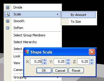
This option will let you scale it by a percent such as 25% of the actual size you've built it in here.
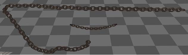
It's now time to make "real" chain so let's see more chain on your models.
Return to top of page
Conclusion
I guess that's it. I hope this helps when making "real" chain in 3DC.
Do you have questions, comments, ideas, criticisms?
My e-mail address is thegrindre@gmail.com.
My web site is http://www.allricksstuff.com for 3' narrow gauge lovers.
I go by the username of thegrindre at most all Internet forums.
But you can call me Rick, most all of my other friends do...
Return to top of page