Wheels With Spokes As Separate Parts: Making Them Rotate Yogether
by Paul DeVerter

A Port City Car Co. Project Copyright © 2004

Overview

Assume that you have built a new vehicle (loco, freight or passenger car, doesn't matter which), and that you are using TSM. Suppose you have constructed the wheels as two or three parts, such as the tires, and the spokes. You did this so that you could change the color of the spokes from time to time, and have that color distinct from the color of the tires.

Also assume that your vehicle will need to have bogies. If you make a short vehicle, and you run it on default MSTS track, and you only have 2 axles, you could probably skip the bogies, and simply parent the wheels and axles directly to the Main part. But, if you run the vehicle on very tight radius curves, you will notice that the wheels will leave the track on sharp curves and move toward the center of the radius.

To counter this problem, you will need to make the front wheels depend from a bogie, and the rear wheels depend from another bogie, and have both bogies depend from the Main. Well, this is just fine for the wheels, but how about the spokes? What are they parented to? This is a tutorial on what to do.

A Practical Example

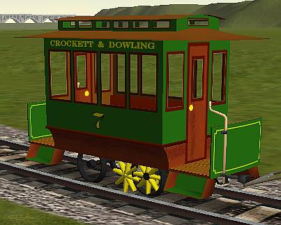
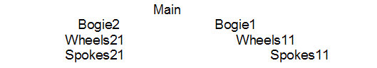
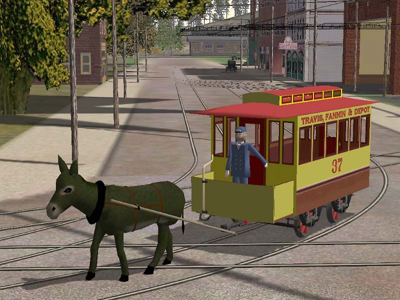
Here is an early incarnation of my standard gauge mulecar, going around a typical short radius curve on a city street. The hierarchy is that the Wheels1 and Wheels2 are both parented to the Main. Everything turns or rotates about the axle as it is supposed to, and the Spokes1 depend from the Wheels1, etc. But the wheels are off the track.

I asked for help from the Port City members, and got two solutions. JW Titus suggested changing the values in the wag or eng file that deal with the mysterious numbers following the r0 line in the coupling section. The thought was that the value, which read "r0 ( 20cm 30cm )" need to be changed to allow more stretch or give in tight curves, and a value of "r0 ( 10cm 40cm)" might work, or even 5cm 45cm.

The second solution was based on one of Tim Muir's cars which had originally had the same problem, but which was corrected by changing the hierarchy. Here is his car pulling the mulecar. As you can see, his wheels are on the track, and mine are not.

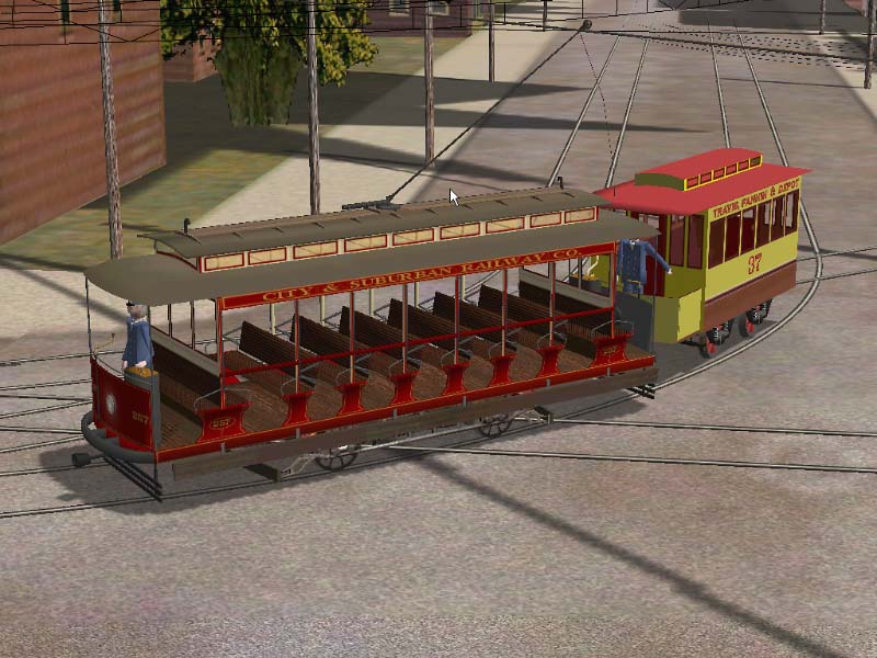
His solution was to insert invisible bogies between the Main and the Wheels. This would allow the axles to track the curve, even though it causes the axles to move a little bit when going around curves.

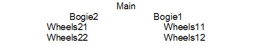
This is what his hierarchy looks like:

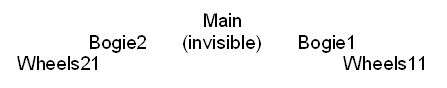
The Bogies are simply single sided polygons, made very small, textured, and hidden in the frame somewhere above the respective Wheels.

I tried Tim's solution and it worked. However by this time I had merged the various parts of the Wheel, so that the spokes, axle, hub, and tire were all one part. So that was the easy solution to making the wheels follow the track.


Wheels and Spokes as Separate Parts

Next came the second mulecar, this time a narrow gauge car, made for 3 foot track gauge. I manipulated the parts for the standard gauge car, and decided to make the spokes yellow, instead of red. Well, if you begin to mess with joined parts, pretty soon everything comes out the same color, whether that is what you want or not. So, I decided to split out the spokes from the wheel, and then color them a shade of yellow.

Eventually, as I built the new mulecar for narrow gauge, it came time to animate the wheels. Everything looked fine in TSM, but when I tried out the car in MSTS, I got an unusual result. I could get the wheels to turn, but not the spokes. Or, I could get the wheels to turn and the spokes, but the spokes rotated in an orbit about the wheels, displaced from the axis of the wheels.

I tried several different hierarchies for the line-up of parts and nothing worked for me. In one instance the tires appeared to slide along the rail, as did the spokes, neither rotating. It turns out that I was not close enough to the tires to see that they were in fact rotating but the spokes clearly were not.

In another the tires rotated along the rail but the spokes rotated about the axle of the wheels, but displaced from the wheel axle. Here is a photo. Notice that the spokes for the front wheel are in the proper place. What you can't see is that they do not rotate; and the spokes for the rear wheel are not rotating about the axis of the wheel, but instead in an orbit displaced from the axis on a lark of their own.

It was back to asking for help and solutions to the problem. Remember the spokes are a separate part from the wheels.

Here are two different variations for the hierarchy. For the front wheels, Spokes11 depend from Wheels11, which in turn depend from Bogie1, and Bogie1 depends from the Main. For the back wheels, both Spokes21 and Wheels21 depend from Bogie2, and Bogie2 in turn depends from the Main.

What I found was that Wheels11 turned (but it was hard for me to get in close enough to see that this was happening) and Spokes 11 did not rotate or turn at all. And for the rear end, Wheels21 turned about their axis, and Spokes21 also rotated, but not about their axis, but instead about an orbit displaced for the axis of Wheels21. All of the parts listed had their centers in the proper place, according to TSM. Putting the centers for the Bogies coincident with the Wheel axles made no difference.

No matter what I tried, I could not make it work. So I sent out another cry for help. And I got four solutions. This is the story of the solutions.


Solution 1 - Join The Parts

Tim Muir has had this same problem with his magnificent trolley cars. His solution is to forget about having separate parts, and simply join the parts so that the Wheels and Spokes are the same part in TSM, and then convert to the s file. Ed Hawkins spent considerable time looking at the animation, and the centers, and came to the same conclusion as Tim, which was to join the parts.

If you texture the separate parts first, and then join them, usually the separate parts retain their pre-joined textures or colors. However you must be extra careful to make certain that you do not open the Part Texture Assignment and then click OK. Instead, you must always cancel out of that box, or you run the risk that the joined parts will suddenly change to the texture (or color) of the primary joined part.

You can use this method and change colors of the Spokes, for example, if you determine which of the colors on the bmp of tga file are those of the Spokes, and then change the color on that texture file, without opening the Part Texture Assignment. So the advantage is that you can change colors for the Spokes, but you have to be very careful in further handling of the joined part.


Solution 2 - Move The Pivot Points in the S File

A much more complex solution was found by JW Titus. His expertise is in analyzing the s file, and determining what the various numbers actually do.

Even though the centers of the Spokes and the Wheels were coincident in TSM, they were not in the analysis of the s file. So, the solution was to uncompress the s file, open it in WordPad, and make a change directly to the pivot point of Spokes21 in the s file matrix. Here is the section of the s file:

Notice the line dealing with Spokes21. The change he made was to the last two numbers in the chain. This returned the pivot point of the Spokes21 so that they were now animated about the proper place. So, the parts could remain separate, and now animated properly in MSTS. The difficulty I saw was that every time you thereafter added a part to the dst file, and created a new s file, you will have to re-edit the s file to correct the pivot points of the Spokes.


Solution 3 - Reduce The Number of Parts

Okrasa Ghia took a look at the problem and decided that the solution was to reduce the number of parts. He felt the TSM pivot points and part hierarchies were correct but I had encountered another bug in TSM. He decided there were too many parts for TSM to export properly, and in doing so the s file would have the wrong pivot points.

He resolved the problem by joining parts to obtain a lower total part count. He joined various parts such as the platform, steps, and brake gear, and then re-exported the file to MSTS and everything worked just fine.

At that time I had about 60 parts and 3500 MSTS polygons. This solution works just fine but limits your ability to change colors after the parts are joined.

Okrasa points out that it is possible to change colors of joined parts by texturing them in poly mode, rather than as a single part. It becomes somewhat of a problem if you have a great number of polygons in the part but it can be done.


Solution 4 - Rename The Parts

The fourth solution is the one that I adopted, because it allows me to continue to add parts and change colors at will. This also came from JW Titus, and what he did was to uncompress the s file, and change the name of Spokes11 in all three places to Wheels12. By doing so, the spokes had acquired a reserved train name recognized by TSM and MSTS. And with this relatively simple change, the Spokes, now Wheels, rotated properly.

Instead of having to make the change in the s file, as JW did, I simply changed the names of the parts in TSM. This means that you need add no animation to the object, as it would be handled internally by TSM when creating the s file. And it meant that a simple part name change would allow me to color and re-color the Spokes at any time. I would just have to remember that they had a new name, and a new hierarchy.

This is the resultant hierarchy, with the change in part names, and it has the renamed spokes dependant directly from the bogies, just like the wheels.

Since the Spokes are now Wheels, everything rotates and pivots properly and the Spokes can be retextured at will.


Technical Notes

Okrasa notes that there is a limit to the number of Wheels available in the reserved train names, namely Wheels11, 12, and 13. When you get beyond that number, the animation is not supplied automatically by the s file. He believes you can add more Wheels beyond 3, but that you will have to add the animation (via the rot file) manually. I have not tried this yet.

The animation is supplied automatically by TSM and MSTS when you use the reserved train names for Wheels and Bogies. It is not automatic for Wipers and Pantographs, and in these instances you must supply it manually. I experimented with Wheels in TSM, and made one project where I manually added the animation to Wheels by inserting a rot file. In checking the resultant s file, there was a complete animation section at the end. I made another project using the reserved train name Wheels11, and in checking the resultant s file, there was a very abbreviated animation section at the end of the s file. Both projects worked just fine in MSTS. So, my conclusion is that you can reduce the length of the s file by using reserved train names for the Wheels, and not using a rot file, thus letting TSM automatically supply the abbreviated animation section to the s file.


Conclusion

Now you know how to have separate parts rotate exactly like they were wheels and still be able to texture them differently at most any time. Of course, there are only three sets of wheels for each bogie listed in the train names. It may be possible to add more if you supply the animation yourself - see the Technical Notes above.

None of this would have been possible without the help of my friends who took the time to puzzle over the problem and come up with solutions. And so, I am pleased to add my appreciation and these credits:

Credits

Tim Muir
Ed Hawkins
James Titus
Okrasa Ghia
Chuck Zeiler - photography