Setting up Signals in MSTS - A Primer
by Russell Beer

General Rules in placing signals

  1. After placing signals do not alter the height of the terrain near the signals as the Route Editor may displace the signals and they will disappear causing problems with editing the route later;
     
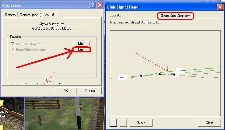
  2. Avoid track database rebuilds as the linking function for junction signals will be lost resulting in you having to re link ALL the placed junction signals.
     
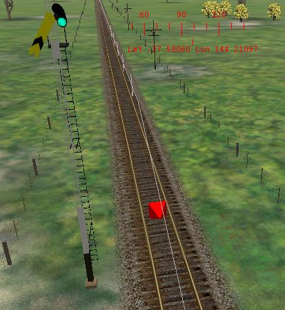
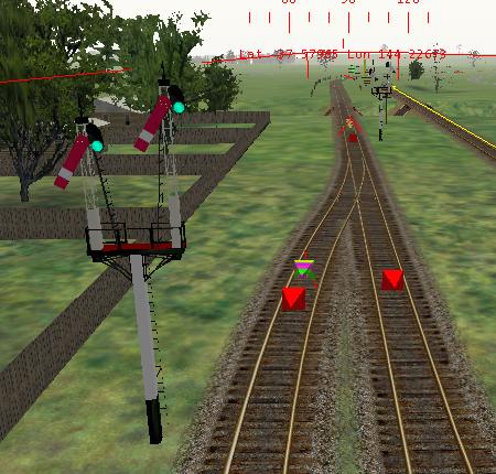
  3. Avoid placing the junction signals too close to the red point data base marker: ensure it is placed on the section of track or further in front of the points;
     
  4. Try to place signals after you have the track work done; you can get away with placing the signals earlier but try to keep well away from the point of work. I usually stay at least a couple of KMs from the end of the track that I am working on.


Distant And Single Home Signals

  1. Place the signal in the desired location;
     
  2. deselect the red marker (that triangular red marker);
     
  3. re-click on the signal itself and rotate to the desired direction: notice how the red marker faces changes direction in accordance with the direction of the signal;
     
  4. now position the signal to the desired height and location on the post (single home signals or distant signals do not need linking).


Junction Home Signals

  1. Place the junction home signals and position as outlined above;
     
  2. These signals need to be linked: click on the red triangle: right-click and you will see a properties dialogue: select the signal tab and you will see this:

    Notice the 2 Link buttons: the upper Link button applies to the mainline stop arm and the lower applies to the branch line stop arm.

  3. Click the top button and you will be presented with this next dialogue:

    The first black dot is the facing end of the points. Click on the lead of the points that you wish the mainline stop arm to apply to: you will see a green line. Close the link signal head dialogue box - this arm is now linked.


  4. Now click the lower link button. You will be presented with a similar link signal head dialogue box:

    Click on the other desired exit: notice the green line has now taken the alternative exit. Close the dialogue box - the lower arm is now linked.
     

  5. Check your work: click on the link buttons again and ensure that the green path lines correspond to the desired routes selected for the signals.

    If everything looks ok close the link signal head dialogue box. At the bottom of the properties dialog box you willjust barely see a status "signal head links set up smoothly" - this means that the paths have been set correctly.


Departure Signals

These are nothing more that 2 separate home signals applied to the 2 departure leads from the loop notice the 2 separate red triangles. These signals do not require linking.

Also notice how all the signals are showing a proceed aspect: after saving and quitting, the next time you open route editor this is what will be displayed: this is normal for the RE.