How To Animate An Electric Loco (And Make Parts Move Using The P Key): Section 6
A Mobile, Animated Crane
by Paul DeVerter

A Port City Car Co. Project Copyright © 2005

Overview

This next project is even more complex than what we have done before. Here we will have a Crane that includes a fixed Motorman's Cab, a Crane Body, a Boom, and a Cable that includes a Weight at the bottom. The animation will include the Weight and Cable moving upwardly while perpendicular to the Main. Then the Crane Body, Boom, Cable and Weight will rotate about the Main, until they are all parallel to the Main body. We have added some Bogies and Wheels, so that the mock-up seems more complete. The street railway companies used very similar locomotives, and, of course, the same principles may be applied to a 250T Wrecking Crane.

In keeping with our other models in this series vivid colors are used, and simple shapes. I have tried to keep the number of parts down to the minimum. You may go back and add complexity and details, as you wish, once you learn the animation techniques.


The Structure

Let's start off by constructing a body, perhaps 9 feet wide, 20 deep, and 1 high. I have colored it red. This we will name Main. You will need to move the Main up above the origin about 3 feet. Then you will have to move the axes of Main back down to the origin - remember constrain x and z, hold down SHIFT, and use the Move Tool to do the necessary. It probably makes sense to texture it now, so do so. The next item will be a wheel. You will want it to be less than 3 feet in diameter, so it will fit under the Main, and onto the top of the track, which will be at the origin. A nice wheel diameter is 33 inches, so do the math, and use the Tube Tool to make a disc that has a radius of 16½ inches or 1.375 feet, a width of say 4 or 5 inches, 8 points, closed at both ends, and structured on the x axis. Then use the Move Tool to move it to the front of the Main, and over one of the tracks. Texture it now - I colored mine turquoise.

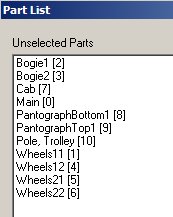
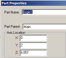
Next you will need a Bogie, so build a cube with the Box Tool that fits under the Main, between the tracks, and perhaps 6 feet long. Move it up under the Main, and color it yellow. Now for housekeeping, you will have to use a Train Name, Bogie1. Set the Part Parent as Main.

Copy Bogie1, and then Paste. Then move the pasted part back toward the rear. If you will look in the Part Properties for Bogie1 you will see that the z axis is approximately 6. So, open the Part Properties for the pasted part, and change its name

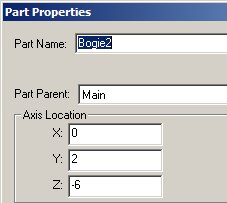
to Bogie2, then change the z axis to read approximately -6. This will result in the two Bogies being equally spaced under the Main. And they both have the correct Part Parent and are both already textured.

Now go back to the wheel and again copy and paste, then move the pasted wheel over to be on top of the opposite track. You could also add an axle, but we don't need one for this exercise. Now select either of the wheels, and press the spacebar so it changes color in TSM. Then move to the other wheel and press the spacebar again, and then press J to join the two wheels into one part. Go to Part Properties and change the name of the combined wheels to a Train Name, namely Wheels11. Since the first wheel was already textured, both should be now, automatically. Set the Part Parent to Bogie1.

Generate Wheels12 by copying and pasting Wheels11, and moving the pasted set back on Bogie1. Rename the pasted wheels as Wheels12. Do the same thing for Wheels21 and 22, putting them under Bogie2, and setting the Part Parent to Bogie2 for each. We have finished parts 0 through 6. We need a Cab for the Motorman, so build a box about 5 feet wide, 7 high, and 4 deep, move it to the front of Main, perhaps a foot from the front edge, and sink it into the Main just a bit. I then was able to delete the un-needed bottom poly of the Cab, and colored the remainder yellow. Again set the parent.

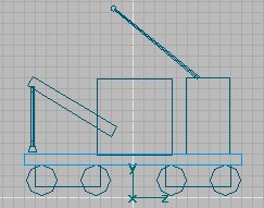
The next order of business is to build the Crane Body, Boom and "part of the Cable". What these parts will do is to simply rotate on top of the Main. Since they are to be animated they will need a Pantograph Train Name, and since they will be moved together they may as well end up being a single part. That is what we will do. You may wonder about the "part of the Cable" - and that is one clever trick. What we are going to have is telescoping parts, because I know of no way to make a flexible part that will roll up on a winch reel.

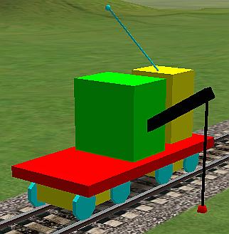
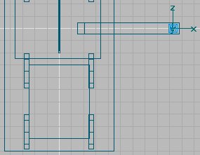
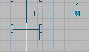
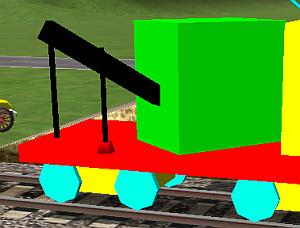
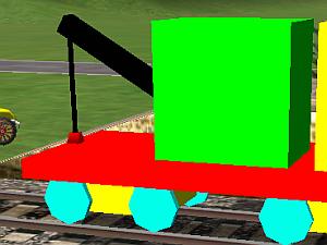
So use the Box tool to make a suitable Crane Body, perhaps 5 feet wide, 7 deep and 7 high. Move it to a position on the top of the Main, approximately in the center. Place the axes in the center of the Body. For the moment call it Body, delete the unseen bottom poly, set the Part Parent as Main, and texture it green. Then create a Boom say 1 foot square in cross-section and 9 feet long. Move it up and into the Body, and angled at some appropriate angle. Delete the poly that is embedded in the Body, and texture the remainder black.

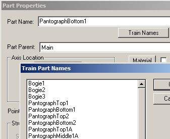
Now for the "part of the Cable", measure the distance that you estimate will be the maximum from the bottom of the Boom, where the Cable will appear to come out, to the ground. I figured about 10 or so feet. So, using the Tube Tool, create a 4-sided tube, approximately 0.1 feet square and 5 feet high, and arrange it to hang vertically from the upper end of the Boom. The top portion will be buried in the Boom, so it does not need a top poly, and the bottom portion will have a similar Cable telescoped into it, so it may likewise be devoid of a poly. For the moment, call it Cable Top, and texture it black. Now select the Cable Top, and press the spacebar, then select the Boom and again hit the space bar, and finally select the Body, and again hit the spacebar; then hit J to join all three parts together. Go to Part Properties, and you should find you have a part named Body, whose Part Parent is Main. If not, then you have joined the 3 parts out of order, and the axes will be somewhere other than the center of the Body. If that is the case, you know how to move the axes, so do so to get then in the center of the Body. Go to Train Names and from the drop down list pick a Train Name that the P key will recognize, such as PantographBottom1. Make sure the Part Parent is Main.

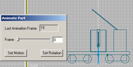
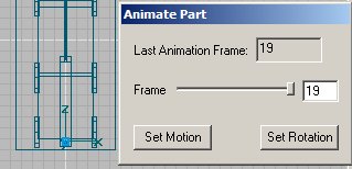
Now would be a good time to set up the Project Properties, so let's do that.

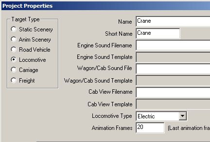
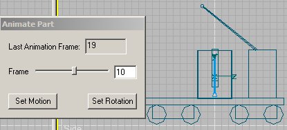
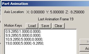
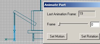
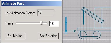
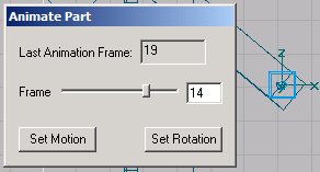
This time I have chosen 20 Animation Frames, mostly to slow the resultant animation down somewhat. We now have a choice: we can either animate what we have so far, or we can build the remaining parts, and then do the animation. Since we are on a roll with the part building, lets finish that up first.

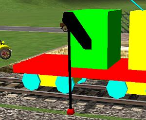
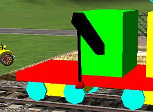
The next part will consist of the Cable Bottom and the Weight at the bottom. You recognize the Weight could be a hook, electromagnet, or some other simulated load. First, make the Cable Bottom, which will be the same as the Cable Top. Texture it black, and place it so that it is telescoped into the Cable Top, and perhaps 6-8 inches above the floor of Main. Then build a Weight of whatever size looks right, put it into and under the Cable Bottom, just off the floor of the Main, and color it red. Now select these two items and join them together. Then go to Part Properties, and change the Part Name to one of the Pantograph Train Names, e.g. PantographTop1.

For our final part, construct a Trolley Pole using the Tube Tool. It may be relatively small in diameter, and have 3 or 4 points, 1 section, and open at both ends. A length of 10 feet ought to do. Angle the Trolley Pole out of the roof of the Cab. Then build a small trolley wheel to go on top - maybe 6 inches in diameter and 2 inches thick, with 6 points. Select both and join them together to make one part. Texture them, I chose turquoise. If you like, go into Part Properties and click Polygon Smoothing. Select a Part Name in Part Properties and you are all done making parts.


The Animation

I believe that you need at least 2 Frames of Animation in Project Properties for wheels to rotate and bogies to pivot. You don't need to do anything other than choose the proper Train Names for the parts, and TSM handles the rest.

But we have chosen 20 Animation Frames, so we are well beyond that number. Let's think about the Animated Crane, and what it is going to do. Remember that we must start with Frame 0 being the extended animation, and the last Frame (here 19) being the running position of the completed model. Now it seems to me we could have about half the frames used to raise the Cable and Weight up from the ground to floor level, and the remainder used to turn the Boom from perpendicular to parallel to the length of the loco.

Let's start with Frame 0. Push the "Ani" button, and then rotate the Boom on top of the Main so that it is 90° to the track. You may also move the Weight to the same place if you like, but we are going to come back and talk about the Weight later. Here is what it should look like in the side view. Since all we are going to do with the Boom is rotate it, push the Set Rotation button. Once again, we are going to take advantage of the

automatic interpolation of missing frames by TSM, we next move on to Frame 10. Once we have moved the slider out to Frame 10, here is what we will see. It looks amazingly like the drawing in Frame 0, disregarding the Weight. So, push the Set Rotation button

once again. From here on, we will start the rotation of the Boom from perpendicular to parallel to the Main. The easy way to do this is to move the slider to the end, namely Frame 19, rotate the Boom to the parallel position, and push the Set Rotation button once again. If you do so, then the Boom will appear to be stationary from Frames 0 through 10, and will then slowly turn from Frames 11 to Frame 19. Leave the Set Motion button alone, as the Boom is not moving anywhere, only rotating.

So, now let us begin animation on the Weight. Select it, and then again push the "Ani" button, and at Frame 0, use the Move Tool to place the Weight is line with the Cable hanging from the Boom, and extending down to the origin. You will need to use the top view, as well as the side view to do this.

Now press the Set Motion button. Next move to animation Frame 9 and move the Weight from the origin upwardly, so that it is at the upper position, as shown in the photo second above (which shows Frame 10, not 9, but they are going to be the same). The two portions of Cable have telescoped into one another, if we have everything properly lined up. Press the Set Motion button once again. This will end the up and down movement of the Weight.

Assuming everything did as you wanted, we need to figure out how to get the Weight to follow the Boom around so that everything looks correct. One way is to next move to Frame 10, and press Set Rotation, then move to Frame 19 and press Set Rotation again. Unfortunately this will not work. The reason is that the axis of rotation of the Boom is not in the same place as the axis of rotation of the Weight. In fact, while it may seem that the Weight is rotating, it is not - relative to its axes. Instead it is moving, not rotating. So, while in Frame 10, and with the Weight selected, press Set Motion.

After having done this several times, I have found that things do not often work as you wish, and the Lower Cable and Weight do their own thing. We will attack this problem next. I have left out the jumping around that the Weight did for me.


Correcting The Animation

We need to understand what the numbers are that we see in Part Animation for the Weight then we need to compare them to the grid, shown in TSM. Next we need to figure out where the Weight should actually be, and make the numbers in Part Animation comply. Let's take a look at the grid from a top view, and likewise at the numbers which show up in Part Animation for the Weight.

Notice on the left photo that the origin (heavy white lines) pass through the Boom and the Weight. This is the x axis, and x is measured from 0 on the vertical axis to either side. Count the grid blocks from the origin to the center of the Weight, and you will see that the Weight is a little over 9 feet to the right of the center. In Frame 0 of the Motion Keys, you see that the x number is 9.285. Since it is positive it is to the right, and it is a little over 9 feet from the origin. Now the y number is 1. This means that the center of the Weight is 1 foot above the origin. Take a look at the next photo. I had moved the origin of the Weight down, so that it is a grid line one foot above the bottom. In Frame 0 we now see that the axes of the Weight are 1 foot above the origin. This means that the y number is correct, because it shows a 1. Finally, for the z number in Part Animation we see it equals 0, and in the photo above, the z axis is on the origin, and should read 0.

The numbers need to be adjusted so that they show in Part Animation what you are seeing or want on the grid. Mine did not and I had to resort to the manual insertion of the numbers I wanted into Part Animation - a tedious process. Likewise, when you move to Frame 9, the only thing that has happened is that the Weight has moved up. If 1 puts the bottom of the Weight at the origin, then 5 ought to put the bottom of the Weight at the top on the Main platform. You will see that for Frame 9, Part Animation shows the only change from Frame 0 is the change in the y value from 1 to 5. Frame 10 is the same position as 9.

Now for the moment, look at Frame 19, above. It shows x to be 0, y to be 5, and z to be a minus 9.28. Now compare that to what you see in TSM and in the grid. For Frame 19, as shown below, the Weight is on the vertical origin line, so it should be x=0. Y has not changed, so it should be above the origin at 5 feet. And now z is on the vertical origin, but a little over 9 feet below the horizontal origin, so z properly reads minus 9.28.

What you have learned here is how to correct mistakes caused by TSM, and more importantly, how to determine what the numbers ought to be, so that you can correct them when they go off on their own, as they surely will.

Logically, you might think that you could next move the slider to Frame 19, and push Set Motion again, and you would be done. I am here to tell you that will not quite do the trick. The Boom and Upper Cable will rotate about their axes in an arc; but the Weight and Lower Cable will move linearly in sort of a chord of the arc, if they move at all. Take a look at these photos and you will see what I mean:


First we have the Weight at the bottom, in Frame 0. Then the Weight has moved upwardly to its upper position, Frame 9. Then, as we rotate the Boom, the Weight travels in a straight line (chord) while the Boom travels in an arc, Frame 15. Then at the end, the Boom and Weight are back together in Frame 19.


Making The Chord Of The Weight Match The Arc Of The Boom

Just what we need, another problem, so what to do? Well, the answer is to do a little thinking about the problem, then a little math, and we will have a solution. Since the Boom describes an arc, and it is done from Frames 10 through 19, perhaps we could set out each of those 9 Frames individually, and then, looking down from the top, use the Set Motion button to move the Weight to the proper position for each of those frames, and get a reasonably accurate curve, instead of a chord. This is a good solution, and since I know it works, that is what we will do. Now we know that the Boom is turning from perpendicular to the Main until it is parallel to the Main - that would be 90°. Since we have 9 Frames available, divide 90° by 9 and we get 10° rotation for each of the Frames.

Now, lets look the Part Animation for the Boom. We have Frame 10 showing y=90 and Frame 19 showing y=0. What we need to do is generate the intermediate dimensions for the Frames from 11 through 18. Well, that is not hard to do. Since we have already done the math, we know that Frame 11 should have y=80, Frame 12 should have y=70, etc.

You can generate those Frames manually, and that will hopefully not be subject to the strange machinations of TSM. Above you see how we have used the Add Rotation button to generate Frame 11, which has not yet been entered. Well, do the same thing with Frames 12 through 18, making only a 10° decrease in the y portions. When you are done, then use the Move Up button to get then in order. Here is what you will have.

This takes care of the rotation of the Boom. Now is a good time to save what you have so far. The next problem will be the Weight.

What we want is for the Weight to follow along as the Boom rotates, and so the theory is to perform the movement of the Weight, clicking the Set Motion button, as we go through the various degrees of rotation of the Boom. It certainly would be nice if the Weight would go along with our efforts. Well it won't, and you will again have to resort to brute strength to make it behave. Anyway here is the idea.

Select the Weight, and then push the "Ani" button, and move to Frame 11. The Weight should still be where it was in Frame 10, but the Boom should now have rotated to the position for Frame 11. We should constrain y, and then use the Move Tool to place the Weight directly under the hanging down portion of the Upper Cable at the end of the Boom. When you have gotten it in the proper place, and adjusted y if necessary, then click the Set Motion button. Then go on to Frames 12, 13, 14, etc.


Problems

Unfortunately the Weight usually will not follow instructions. You may find that it goes off on jaunts of its own, such as seen here. Not only are the x and z wrong, but the y has moved down as well. All I have been able to do is to keep trying until the animation surrenders. I am going to offer three thoughts - save often, and manually insert numbers you feel are correct in Part Animation. Patience is a virtue. When all else fails, I have had luck in deleting the Weight and Lower Cable, and then making them over again as new parts, and starting in animating those parts again.

Let me show you one other problem with this sort of animation. Recall the Boom is rotating about the Central Axis of the Main. However the Weight is not rotating about anything, instead it is moving. So this means that the Weight, as it moves from out at 90° to in at 0° is not rotating. For example, look down on the Boom at Frame 14. The axes of the Weight are not rotating with the Boom, but are simply moving from place to place

and remain parallel to the Main, and the grid lines. Consequently, if you use this technique to animate an object at the bottom of a Cable, make the object round, and it will appear to rotate, even though it does not. If you were to use a hook, the hook would look fine in Frame 19, but not in the intermediate Frames, because there is no rotation. On the other hand, if you were lifting and placing onto the Main a piece of rail, you would probably wish the rail to remain parallel to the roadbed (and Main), and not rotate.


Final Corrections

The big problem is that the Weight does as it chooses when using the Set Motion button in TSM. One thing that helps is to adjust the numbers in Part Animation. As previously mentioned, you know the Weight at Frame 0 should be close to y=1, at Frames 9 and 10 y=5, and in fact y=5 all the way to Frame 19. Make that change in Part Animation. The next thing you know is that as the Weight moves from Frame 10 to Frame 19, the x number gets smaller because the Weight is moving from along side the Main to on top of the Main. At the same time, the z number should be getting larger, in a negative way, because you are moving the Weight from the center of the Main to the rear of the Main. Look at these numbers below. Notice how y is hovering about 5. So what to do.

Change the y numbers to 5. That seems to help stabilize the animation. Then remember your geometry from high school. In plotting a circle, in the x and z plane, the x and z numbers seem to be some sort of reciprocal. Look at this photo.

Here I have changed the appropriate y values to 5. But notice the x in Frame 11 is about the same as the z in Frame 18. And the z in Frame 11 is about the same as the x in Frame 18. Why is this? Because we are talking about 90° rotation of the Boom, and Frame 11 is 10° off one ordinate, and is Frame 18 is 10° off the other. Make them the same and you have symmetry. You will see the same thing in the other intermediate values.

The lesson here is that TSM gets confused, and the best way to get the parts to move where you want them to is to do the math and insert the proper numbers in the Part Animation box and not rely on the Set buttons at all.


Lessons Learned

This animation involved having one part rotate about one axis (here the y axis) and another part moves up and down in the same axis (again the y axis), and also moves to different positions in the other two axes. It confuses TSM. What to do?

First, you must read the instructions in the "How to Animate a Scenery Object" tutorial. The problems are the same - things do move around without your intervention.

Second, no matter what you do, TSM will do its own thing when you press the Set Rotation and Set Motion buttons. So, you must be prepared to enter all the data directly into the Part Animation window, and to do so, you must understand what the data should look like. The grid will tell you approximately what the numbers should be.

Third, try, try, and try again. If you know the approximate number that should appear, stick it in, and maybe it will stick, and the animation will act properly.

Fourth, the Part Animation window is the place to enter numbers, when TSM Set Rotation and Set Motion buttons do not work.

Fifth, you must be prepared to delete parts that do not act properly, and redo the whole animation of that part - something that was covered in the previous part of this series, as far back as Animating Scenery.

Sixth, save often, and in fact, not only save, but also close out of TSM, and then reopen again.

OK, we have finished the Crane with a Boom that rotates, and a Weight that raises and lowers, and also appears to rotate and follow the Boom. An example of a Scenery Object, which uses essentially the same motion and rotation, was animated by Ed Hawkins for use in the Thompson Expansion for the Canton-Suddenly Route, just released by Rich Garber. Ed was kind enough to show me how he accomplished the animation of the Scrap Metal Crane - a fine piece of work.

Time now to think a bit about what the eng files should look like when you want to make a freight car using the capabilities of the electric locomotive, so the next section will talk about that.