Constructing A Steam Loco Using Train Sim Modeler
Part 3

by Richard Osborne

Animating Rods And More Big Lumps

Let's move on to animation of the rods. First we need some rods, these will be made from 3 component parts & joined in a particular sequence. I'll explain as we go.

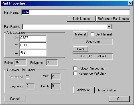
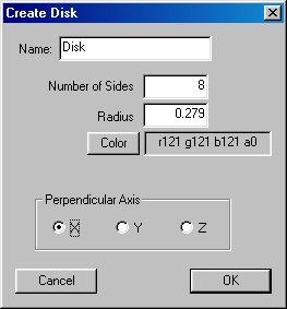
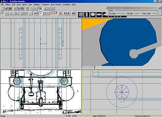
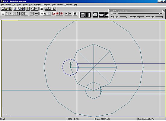
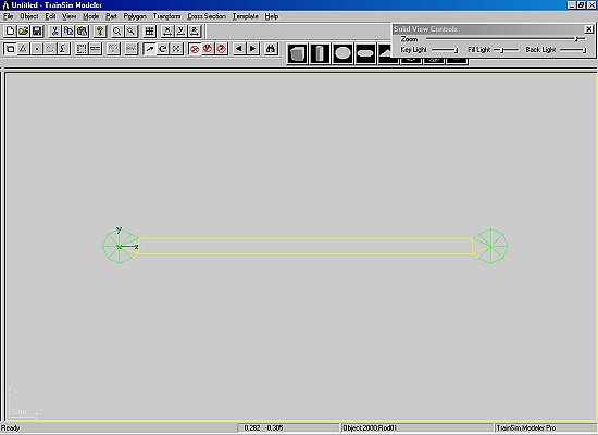
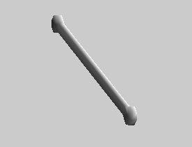
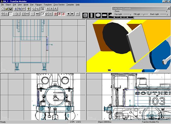
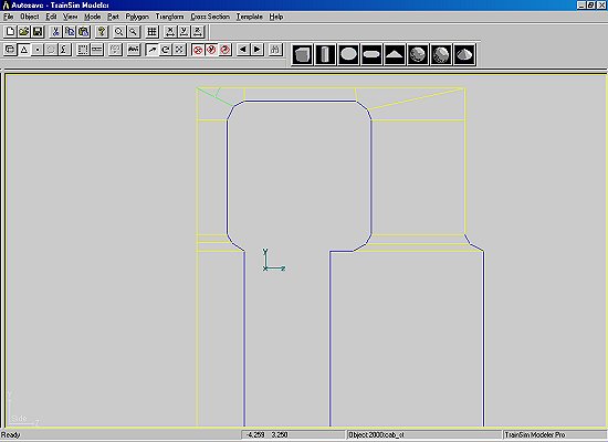
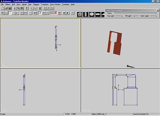
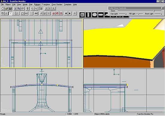
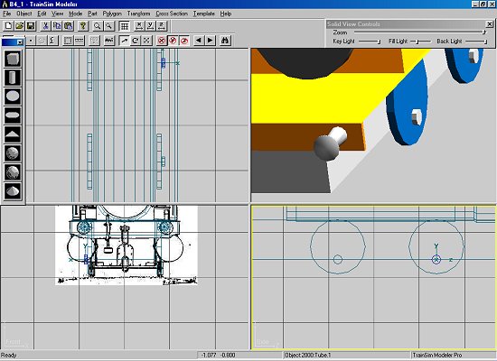
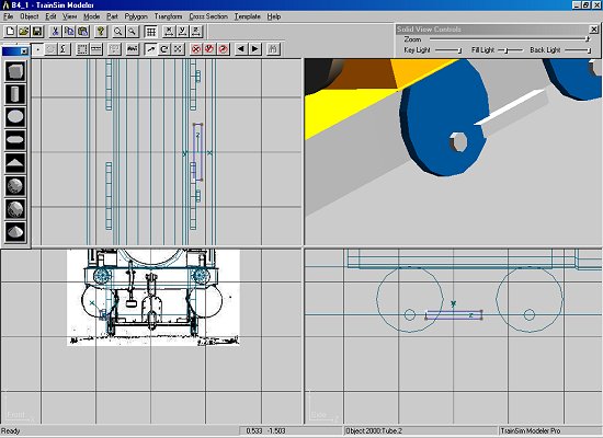
The driving wheel end, just a tube with the right side closed. Notice it's been set to the axle coordinates. Copy, paste & reset to the axle coordinates of wheels1. We have both ends of the rod to exact length.

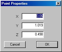
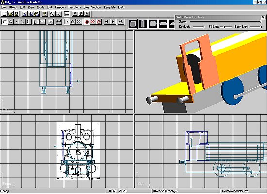
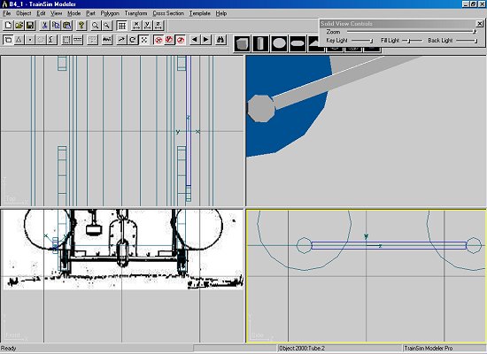
For the joining part draw an open square tube - nurdle it about until it's a decent fit. I do about 90% of my drawing in 'point' mode - other people will do it differently. Use 'v' to get it square. 

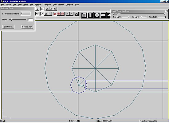
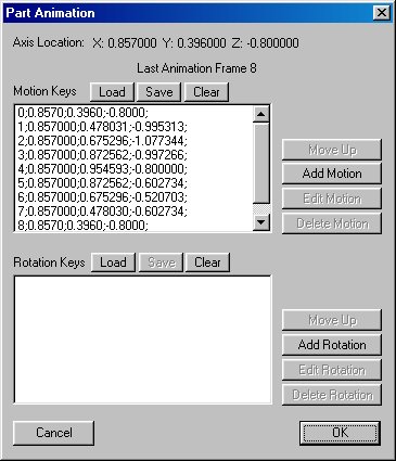
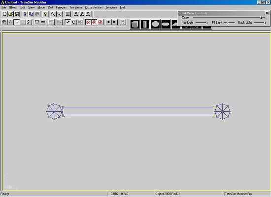
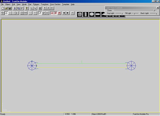
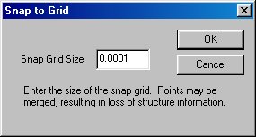
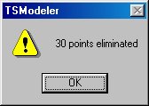
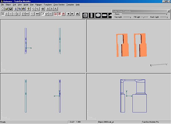
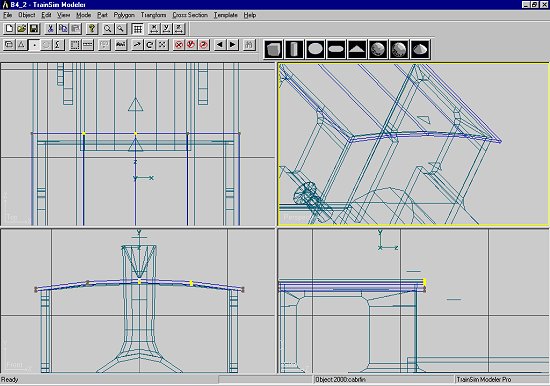
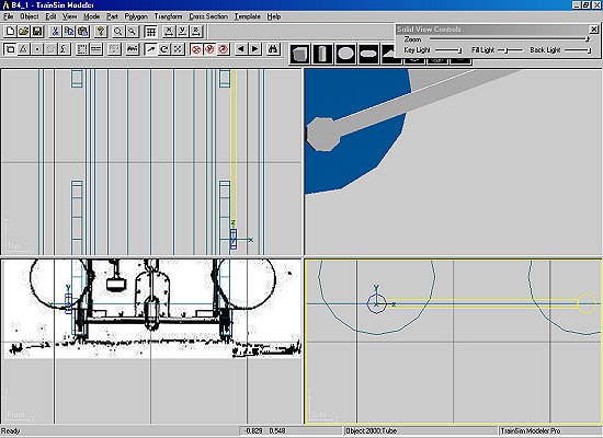
You'll have noticed that each of the 3 parts has its own axis. We want the rod to have the axis of wheels2 - the first part. We need to join them in such a way that the first part is selected last. Highlight the front part, the rod & finally the rear part. Double check - it's a fiddle splitting again. 'Part' then 'Join Selected', F2, take one of the Train Names - rod01, parent 'main'. I'm going to come back to the rods & show how to split, improve & rejoin it, using 'Snap to Grid'.

Why not take 'Wheels2' as parent? Think of your dinner going round in the microwave, it stays motionless on the plate and rotates relative to the oven. Then think of Buster Keaton sitting on the coupling rod in "The General" - he is motionless relative to the rod. We could have 'Wheels2' as parent - we'd have to introduce a rotation counter to the rotation of the wheel. Why complicate life?


Animating Rods

We've found that animating wheels has no great secrets - neither have rods. Remember these rods will have MOTION only. We have to introduce a marker for the movement. Again there are many ways of doing this, I'll sometimes use a dummy crankpin. This way is simple & it works. 

From the primitives draw an 8 face polygon. The stroke of a B4 is 22", hence 0.279.

F2, position the disk at 'Wheels2' axis.

We have the rod at BDC. To make life easier - in the side window, right click & go to 'Expanded View'. You'll have seen that we have 9 frames for 8 animation movements - 0 & 8 are identical. Make the animation button live - it'll be at 0, press the Motion button, ignore Rotation. Without moving the rod slide the animation to 8 & press again. We'll double check the list with F2.

Now bring the animation slider to 1, the wheel will rotate, the disc & rod will stay still. Move the rod, you're going clockwise, until the axis is at the 1st point of the disk. A picture's worth a thousand words.

Press Motion. Repeat for the other points, the slider's not as friendly as it could be. Next position, move rod, press 'Motion'. repeat, finish, check the motion. F2, verify the motion, 0 & 8 should be the same as the axis coordinates given at the top of the page. If not highlight the line & edit. Go back to the perspective view & check it. Save the rod & the project.

Load the rod, F2, make it negative in 'x', rename it 'rod02', flip in 'x'. It will work perfectly well like that BUT we want better than that. Prototype wheelsets are quartered, we'll do the same. Some people will explain how to progress the motion - I assure you it's quicker to start fresh. F2, notice that "Motion" appears by the animation button. Open the page & clear the motion. Move the rod either straight ahead or straight back, properly "trailing" or "leading". There's no right or wrong, sometimes locos of the same class were set differently.

Do exactly the same as for Rod01, if one rod overtakes the other you've made a mistake. Remake the project, go into trainsim & take a look.


Improving And Re-working Parts

The rods are a bit clumsy, we'll improve them somewhat. Open another TSM, after minimising the first. Load Rod01.

We're going to make it more homogenous & improve its looks a bit. To do this we'll need to split the part. This is why we opened another TSM, here we have just 2 parts. In 'polygon' mode find & subdivide both 8 sided polygons. I can't really give a blow-by-blow summary. You'll see which parts to split & move. Experiment - you haven't saved anything yet. You'll be using the multiple point tool. 

Points won't join to other points in the same part. Hence splitting, even if it's just 1 polygon. Takes longer talking about it than doing it. If you look in the parts list everything will still be called Rod01. 

You'll find that you're going to be 2 polygons short. Copy an individual polygon, paste & move. When you're satisfied rejoin the parts. Cycle through the parts & highlight with the space bar. Remember we want the part with 'Wheels2' axis to be the last. 

Hidden from view TSM still isn't satisfied, test the part by smoothing it in F2 - it won't smooth. There's something else we need to do. Go to 'part' menu, halfway down is 'Snap to Grid'. This feature gathers doubled points within a certain distance & singles them. It's an internal function of the program we're not actually drawing to a tenth of a millimetre. Press, you'll see the default figure is 0.1. This is way too big, we want a figure of 0.0001 - something impossibly small. Our points are coincident as we used 'v'.

Look what's happened. We've lost 30 points from just this one part - that's 60 bits of extra information that MSTS doesn't have to lug around with it - just from 2 rods.

Notice that it's also smooth.

While this proves that snap to grid has worked the rod looks more like a dog's bone so take smoothing off the part. Save the part; don't transform it into Rod02 yet. Load rod02, F2, animation button & save the motion. Delete rod02, load the new rod01 & transform it to rod02. Load the motion you've just saved. Save the part. Minimise this TSM - it's too easy to lose parts. Open the first TSM, delete both rods & load the new. Check that they both have 'main' as parent. Check the animation & save the project. It would be a good idea to back-up onto disk.


Cab And More Big Lumps

There are dozens of way of making objects like the cab of our B4. For this demo I'll build it from a series of boxes. This will give an exterior, interior & cab coaming. We could equally make a flat side, copy & flip it, then make the rear parts. 

Start with a box which fits behind the tank. Rough it out by eye.

Let's get accurate; snap the 2 points closest to the tank.

Point mode, F2, check the 'x' & 'y' dimensions. Go round the other points & make the box part regular. 

Copy the part, paste & move building up the cab shape. I've used 13 boxes in total. 

Now with a scrap of paper to hand ( to jot down figures in F2 ) tidy the boxes into shape; make the verticals vertical, the horizontals horizontal. I've again opened another TSM. Notice this is Autosave, I'd forgotten to save the part. Remember this feature - you'll lose a maximum of 10 minutes work.

If you can visualise inside the cab you'll see bottom, top, front & rear faces which we don't need. Even with a small loco like this we want to lose all unnecesssary polygons. In 'polygon' mode go round & select all unseen polygons. Split part, into 'part' mode, delete the part. From this cab side part I deleted 38 polygons, leaving 36. For both sides that's 158 polys saved. I'd separated the polygon which will be the rear horizontal part of the coaming. 'Snap to Grid' - another shed full of points saved. Don't try to delete polygons - you'll have orphaned points to confuse MSTS. Always make your polygons into parts & delete them - even just a triangle.

In order to have the interior smaller than the exterior grab points & move them inwards. Save this part as cab_st.

Load cab_st, F2, negative in 'x', rename cab_pt, flip in 'x'. You now have a matched pair of cab sides. Before texturing I'll delete the bottom front polygon, extend the tank side & join the part.

Make cab front from a 7 sided polygon, you'll need to copy & paste it, in F2 make it alphanorm in the 'materials' box; these parts will use transparencies.You need 3 copies; cab front forward & rear ( flipped ); cab rear forward & rear (flipped). Snap with 'v', F2 to tidy up. It's not a bad idea to save the loco with a different name. If there's a problem you can always reload an earlier version & add newer bits - that's another habit I learned with the earlier flightsim programs.

It's looking more like a loco now. I've substituted my usual grey blank.ace. 


Chimney And Dome

I shall add a few more bits before making the cylinders. The dome starts as a sphere, cut in two - discard the bottom half. 

How many sides?

This is entirely preference remembering the trade-off between detail & frame rate. I remember, from the best flightsim how-to, the tip that the cockpit surrounds gave the identity to an airliner. Buffers, chimneys & domes do the same for a steam loco. Make a chimney too fat or with the wrong taper - it'll never look like the prototype. You can make the best wheels that ever graced a virtual loco - nobody notices.

I've made this dome with 12 points - you'll almost certainly need 2 sections for the base in order to make a convincing mating surface with the boiler. So, with half a sphere & a tube snapped with 'v', squeeze & pull your dome into shape. 'Snap to Grid' & save. I'm a lazy bod so I'll use the dome as a basis for the chimney. You know the proceedure now. I've split off the top section to use as the inside of the chimney - the inverted cone - gives a good effect for just 12 triangles. Roughly place it & snap with 'v'. 


A Couple Of Brilliant Features

TSM is over modest - tucked away are some very useful features. One is the ability to hide parts from view. This doesn't affect the parts in any way. You could always hide parts by deleting them but this rather defeats the object of the exercise. We'll hide the dome so that we can see the chimney better.

Isolate the dome in the parts list, 'OK'. Go to the 'Edit' menu, about 2/3 of the way down you'll see 'Hide Selected', press. Please be careful in this list - it's very easy to press the wrong thing & lose parts. That's why I suggested you practice on one of the samples. Make a note of the hot keys - saves time. Notice the dome is hidden in the perspective view as well. 

I made the cab roof from an open 8 sided tube - there's an edge which is very noticable on this loco. (I've got to admit to cheating here - I took the screenshot after I'd made the part). 

To make the closing rectangles. In 'point' mode lasso 4 points - it's pretty obvious which - go the the 'polygon' menu. Only ' Make Polygon From Selected Points' will be black & active. Press & you'll see that a polygon has been added to the roof. Repeat for the other polygons. Don't try to make a closed tube for a part like this - you'll get tied in knots. NB polygons like these won't cause any problems, if the polygon is more square TSM sometimes gets confused & draws the polygon crossed. There is a way of correcting it - cross 2 points - into 'polygon' mode. 'f' for flip, a small screen appears with Yes to flip selected points, No to flip entire polygon. More experimentation needed here. Sometimes it's just as quick to introduce a polygon & glue it on - especially on a curved surface.

Here's another useful dodge. Sometimes it's useful to lose the solid modelling. Go to 'View' menu, 'Perspective View' & turn off 'Display as Solid'.

One more thing you'll notice about TSM; I have a program running which tells me the RAM usage. It's VERY greedy with memory. It takes memory until it'll lock up. Probably won't until it has a big file but every now & then, after one of your frequent saves, come out of TSM - maybe reboot the computer while you make another coffee. Reload TSM & start fresh. Remember if the worst happens & it locks up you always have Autosave.dst.

You'll have noticed some little triangles in the drawing. These are for the steam & smoke effects. Draw a small triangle & place it above the chimney. F2, to the right of the 'Part Name' box you'll see 'Reference Part Names'. By definition these parts aren't drawn by TSM - they're to identify animation functions or, in this case, additions to the .eng file. Choose fx_stackFX , remember we have to interpret from the American. Do the same for the whistle, safety valve & cylinder cocks. The other function is for injector overflow. While we're here make a note of where you thing the 'HeadOut Display' should be. The default will be for the Scotsman - or in the first wagon of our train! Make sure that the 'Project Properties' has been changed from B4_1 to B4_2 & remake. The screen will have everything ticked. Go into the Consist Editor & make up a train for B4_2. The .eng & .wag files can be read & edited with Windows wordpad - you may have to associate first. This time open the B4_2.eng file & see the train effects that have just been added. Find the 'HeadOut' line & alter it. Make the first value negative, probably -1.2. Civilised locomotives are left hand drive.

Now we should have a loco with smoke from the chimney & a little wooden whistle that would whistle.


Copyright Notice

Please read my copyright notice (click here)