Achieving Perfect Car Length Parameters
by Yuri Sos

**(updated 2 June 2006, using input from Ian Bowles aka "gallop3", Joe Morris and Lukas A Lusser aka "Swissie")**
*** Updated 19 Sep 2009 with important Centre Of Gravity fix information discovered by L W Shell and Jeff Kraus-Yao ***

Overview

Every now and then you come across a model like this................

In this case, we're dealing with us2freightcar5; frustrating as the train rumbles past with wagons separated by a metre or more distance.


Defining The Problem

Checking the bounding box in this model (press Ctrl + : the + key on the numeric keyboard), we can see that it's ok as far as the BB is concerned: in fact this particular model couples and uncouples correctly, but the vehicles remain separated.

So how can we reliably repair wagons such as these?

The first thing we need to know is "What is the correct length of this vehicle?"

The answer lies in using Paul Gausden's magnificent Shape Viewer and then performing a little judicious editing of the model's .WAG file.

Open the model in Shape Viewer and press Ctrl-B to see the dimensions of the wagon in a visual sense (the red shaded box in the image above), then press Ctrl-C to bring up the pop-up box listing the dimensions of the model. It should be noted here that these dimensions are calculated from the shape file itself with no reference at all to the .SD or .WAG file.

The key dimension to read here is the length of 20.269m, say 20.27m (we don't need more than two decimal places and there's some evidence to suggest that these long numbers may delay or even confuse MSTS). This is the complete length of the model from coupler to coupler.

Open the model's .WAG file in the Unicode-aware editor of your choice. It will look something like the image below.

You will note that the length in the .WAG file is shown as 21.3m. This is where the problem lies.


Correcting The Errors

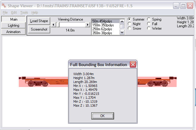
It's been stated elsewhere that the length of a model should be calculated as the distance between coupler centres. So if we take the end-end dimension from the .S file of 20.27m and subtract say 0.4m, you'll end up with a coupler centre-coupler centre dimension of 19.87m.

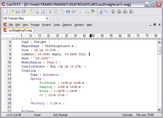
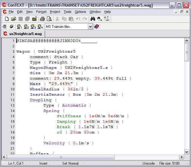
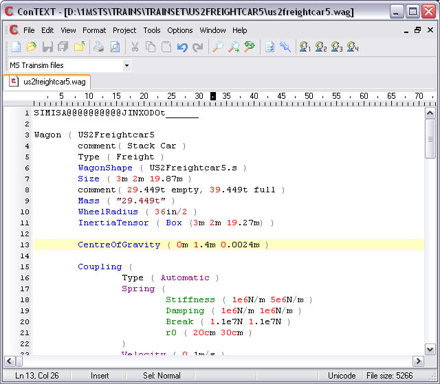
Change the numbers in the Size line to read 19.87m (as in image above).

Change the numbers in the InertiaTensor to read 19.27m (as in image above). The InertiaTensor length is inter-related with the coupler damping characteristics and should be the same or just slightly smaller than the actual Size.

Save the file.

While you're there, check the .SD file (see below).

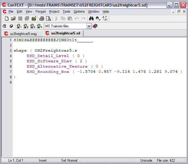
Examine the ESD_Bounding_Box line.

Firstly, what do these numbers mean? These numbers define the limits of the bounding box from the centre of the model in the format

ESD_Bounding_Box ( front-x lower-y front-z rear-x upper-y rear-z);

the parameters are in meters:
x: left negative, right positive relative to origin;
y: positive above, negative below origin;
z: positive forward of, negative to the rear of the origin.

So an ESD_Bounding_Box ( -2 0 5 2 3 -5 ) would define a bounding box 4m wide, 3m high and 10m long, extending 2m either side of the origin of the model, up 3m from the origin of the model and 5m fore and aft of the origin of the model.

Several things to check:

  1. The second parameter (in this case 0.957m) should be 0.6m or higher as it delineates the lower limit of the bounding box: some models have this figure as low as 0.01m which may cause derailments on uneven track or level crossings.

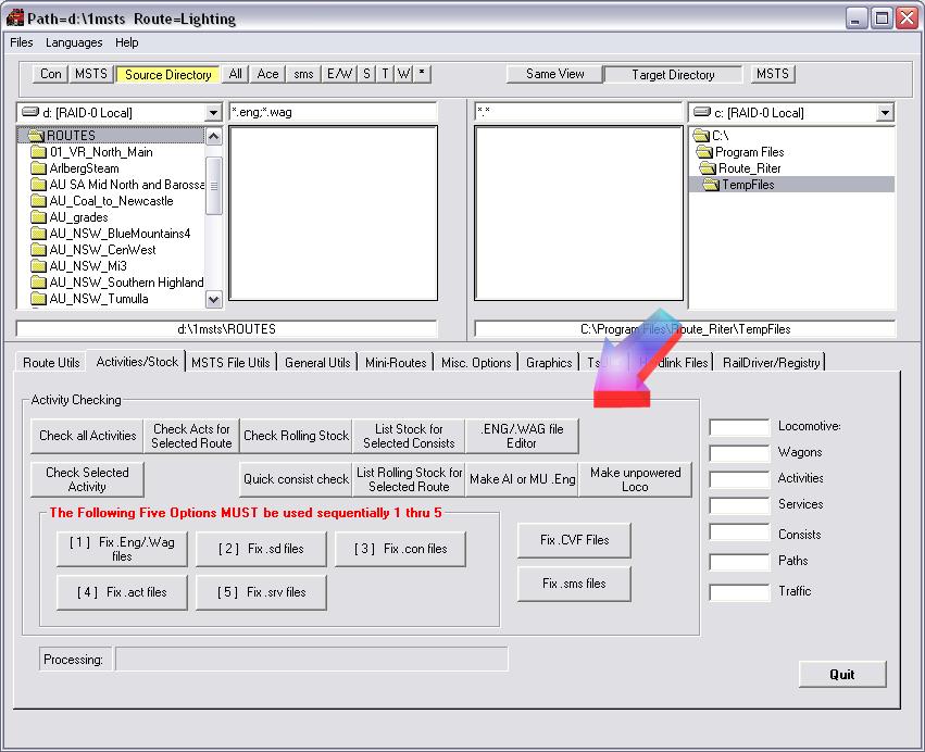
    Route Riter 6.1.63 or higher now has a button under "MISC" enabling you to change all the minimum height bounding box values to 0.90.

    In the case of a flatcar, such as this one, it might pay to increase the height of the bounding box to say 2.5m to ensure it doesn't get "run over" by an adjacent vehicle.


  2. Add the third and sixth figures (ignore the minus sign on the third parameter): these two figures should add up to a figure less than the model length figure in the .S file. The easiest way to achieve this is to change the third parameter to Shape Viewer's min Z figure plus 1 and the sixth parameter to Shape Viewer's Max Z minus 1. This pretty well always leaves the bounding box covering the physical shape of the wagon excluding draft gear and couplers.
     
  3. Truncate all values to two decimal places.
     
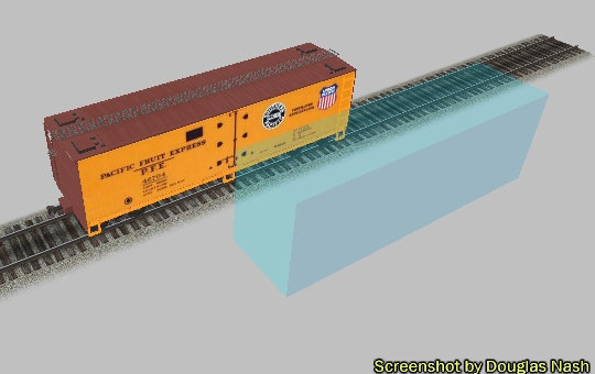
  4. Make sure the width and height parameters are correct. Some bounding boxes are way out width-wise and you may get collisions with vehicles on adjacent tracks: set the width (1st and 4th parameters) to -1.47 and 1.47 on all (standard gauge) rolling stock.

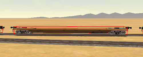
    See image below for an example of a Bounding Box WAY out of line.

    Example of a badly defined Bounding Box

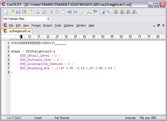
When you've done all the above, this is how your .SD file should look:

Final appearance of .SD file

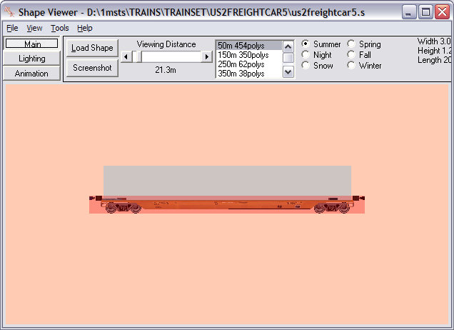
And this is how it should look in Shape Viewer - from the side.....

Side on view in Shape Viewer

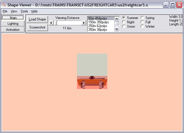
....and from the end......

End on view in Shape Viewer

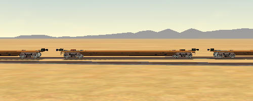
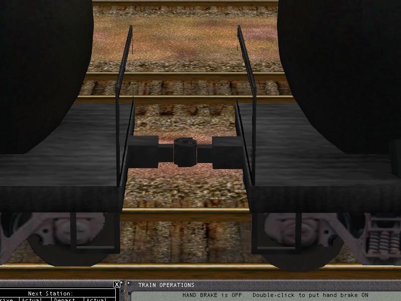
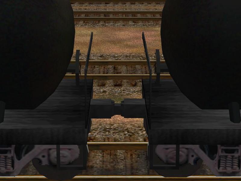
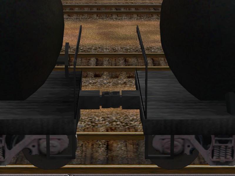
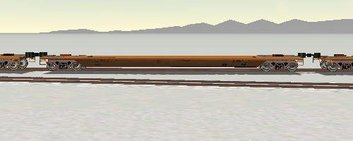
Now let's look at this models in the simulation again. You can see that these wagons now appear correctly coupled and couple and uncouple correctly.

Consequences of Too Long a Bounding Box: the BB will prevent the engine or car from properly re-coupling.
Consequences of Too short a Bounding Box: the shortened BB prevents the car from being stopped in buffer-type collisions at the end of track before it "falls off the rails".

You may wish to alter some of the figures I've presented here, but at least you have a formula for establishing correct dimensions for model length and bounding boxes.


Dealing With Oddly-Spaced Wagons (the Centre of Gravity Fix)

Route Riter (v6.4.5 or higher donation-ware version) already performs the corrections in the tutorial above, but the CentreOfGravity fix will be included in RouteRiter v7.1.42 or higher.

Once you've corrected all the parameters above, you still may occasionally notice that wagons are not equally spaced when one wagon is flipped relative to its neighbour. The couplers may be further apart or more bunched up than when all the wagons are "facing forward" or unflipped. This occurs when the model is not centred on the Z-axis and thus the couplings are not equally spaced when the car is flipped.

Using the figures derived from the Ctl-C window in Shape Viewer, adjust or add a CentreOfGravity line to the model's .WAG file so that the "z" value is changed using a value calculated by the formula

inserting the appropriate values for Min Z and Max Z.

Continuing to use the USFreightCar5 example above............

the formula for z would read

Note that this resultant figure can be either positive or negative. Adding the line

CentreOfGravity ( 0m 1.4m 0.0024m )

will now correct this car and couplers will be evenly spaced whether the wagon is flipped or not.

Whilst this is a trivial change in this particular wagon, this alteration can make quite a difference in wagons such as these tank-wagons (images below): Shape Viewer reported these wagons as having Min Z -8.4845 and Max Z as 8.30134 - a difference of 0.18m (or 7 inches for those metrically challenged): this could translate to a 0.36m/14" variation in the gap between wagons.

  • The first image shows the wagons in a normal consist;
  • the second with the trailing (right) wagon flipped relative to the other (left) wagon being "normal"; and
  • the third with the leading (left) wagon flipped relative to the other (right) wagon being "normal".


Adding a line CentreOfGravity ( 0m 1.4m -0.0916m ) resulted in evenly spaced wagons, flipped or not. As demonstrated by the images above, even a small offset of origin from the centre of the model can make a large difference visually.

Route Riter (v7.1.42 or higher donation-ware version) includes the CentreOfGravity fix as part of the Fix ENG/WAG file editor.


Thanks to L W Shell who first noticed the effect of a change in CoG and to Jeff Kraus-Yao for the formula for another MSTS fix.


Executive Summary

Quick reference summary of values to be changed:

  • Get true length of model from Ctrl-C in Shape Viewer;
  • Set length in the Size parameter in .WAG file to length minus 0.4m;
  • Set length in the InertiaTensor parameter in .WAG file to length minus 1.0m;
  • Set length in .SD files to values 1m less than min Z and and max Z from Ctrl-C in Shape Viewer;
  • Check width and height parameters .SD files; truncate all values to two decimal places.