Using The Auto-Placement Function (gantry.dat) in Route Editor


by Yuri Sos
with a great deal of help from others such as
Chris Schwan, Lukas Lusser, Phil Voxland
and Jim Ward

Overview

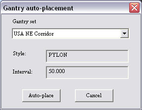
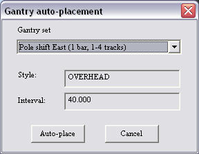
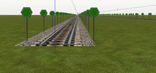
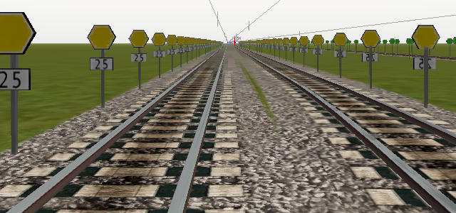
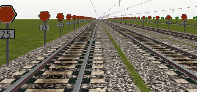
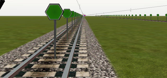
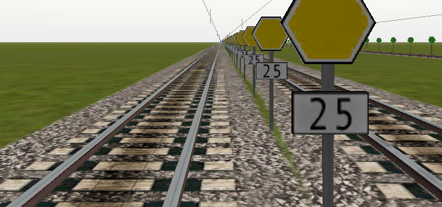
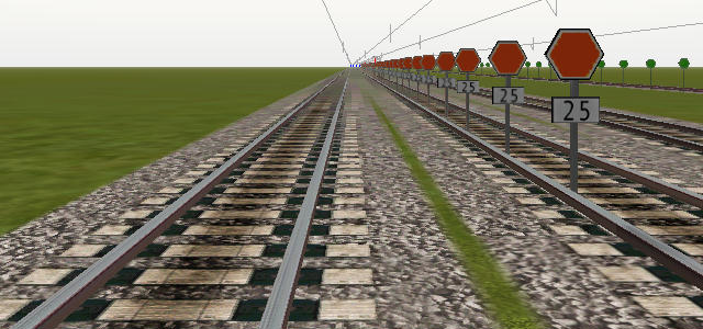
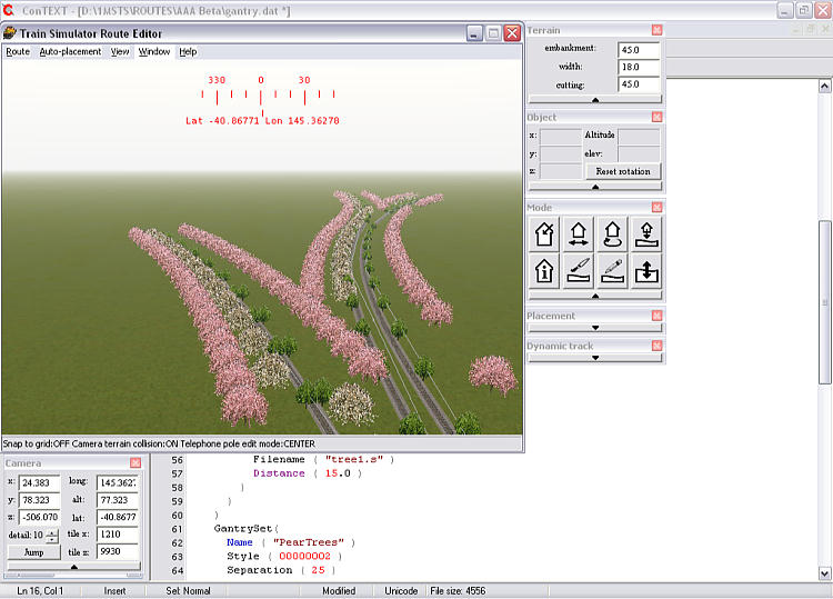
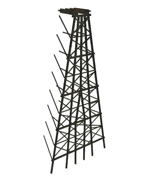
The Auto-Placement menu option in RE is an extraordinarily useful tool which enables you to automatically place gantries or other specified shapes at regular user-determined distances along the edge of tracks within a specified tile, saving you hours and hours of work. The gantry.dat that the Auto-Placement uses allows you to select different shapes for double triple and quadruple or more track sections which the function then places correctly (most of the time). You can select single shapes that are located on either side of the track or use a single shape that spans the track.

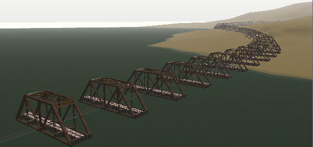
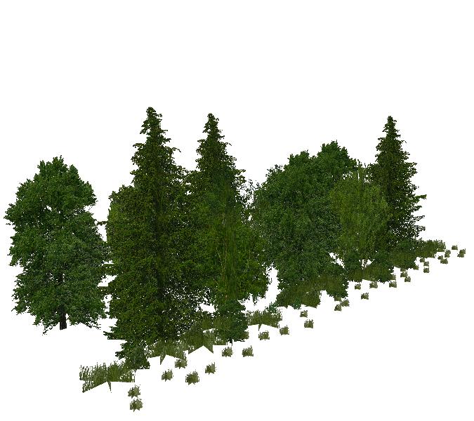
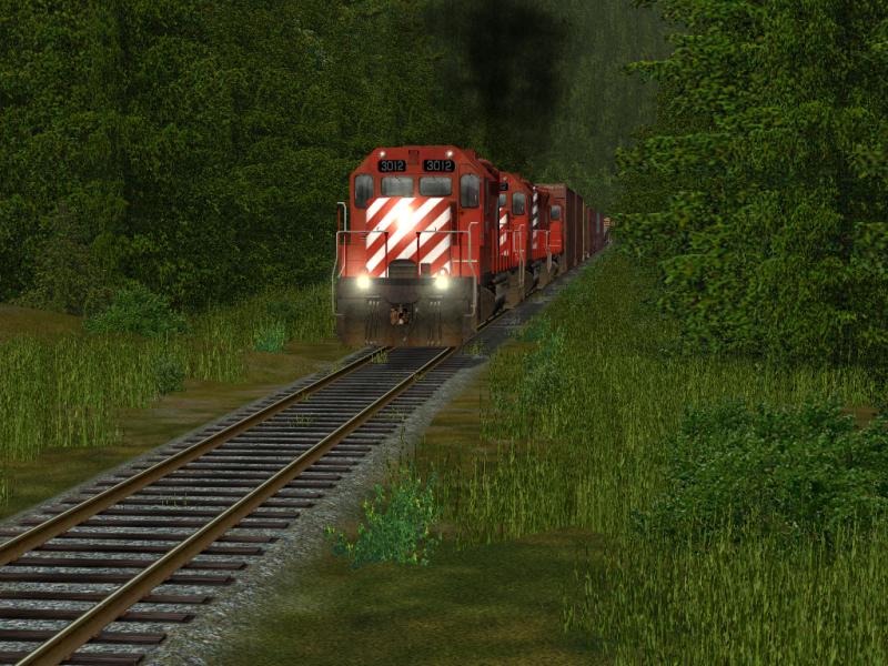
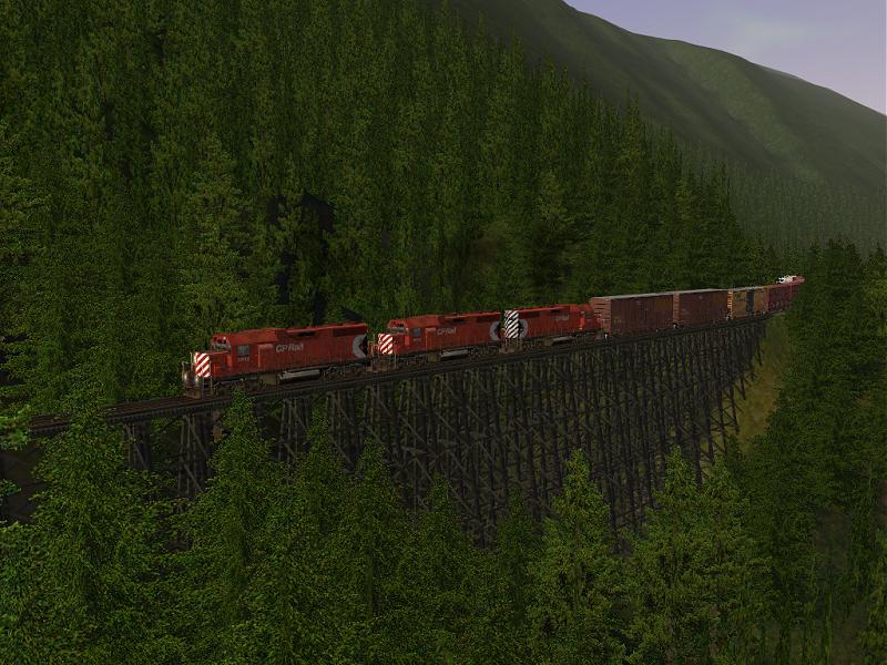
Though originally designed for overhead gantries and poles, Joseph Realmuto and Wayne Campbell demonstrated a use for making fences in 2002. In July 2004 Chris Schwan expanded this, creating tree clumps to populate the fringes of the right-of-way. There is really no limit to the number of uses for the Auto-Placement function.

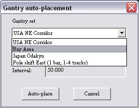
There seems to be no limit to the number of Gantry Set entries you can make in the Gantry.dat file and once you have placed the shapes using Auto-Placement you can individually move/rotate or delete shapes without affecting the rest of the route.

Some limitations: yards cause the Auto-Placement process some problems. Placing shapes away from track edge mean that some shapes may be suspended in mid-air beside embankments or buried in the sides of cuttings. Scale Rail users should also note that all gantries will need to be set as terrain objects or else you will have alpha bleed through.

Overall the advantages far out weigh the minor disadvantages.

As Jim "Sniper" Ward says "....saves an astonishing amount of time, I wish somebody had thought of this 3 years ago!"


Structure of the GANTRY.DAT file

The Auto-Placement operation uses data found in the gantry.dat.

The gantry.dat file structure is much the same as many other accessory route files: it is a Unicode text file, so you'll need a Unicode-aware editor such as Wordpad (Notepad in XP only) or my favourite, ConTEXT.

The file is arranged as a series of nested instructions, so you will need to be careful so that your brackets match up. I'd recommend grabbing a default gantry.dat file and adding sections as required.

The basic structure of a gantry.dat file is as tabulated below - xxxx indicates an alphanumeric string is required, nnn indicates a number is required. Each of the major parameters is linked to an explanation of how that parameter works.

Tr_GantryFile (
GantrySets ( nnn
GantrySet (
Name ( "xxx" )
Style ( 0000000n )
Separation ( nnn )
GantryTable ( nnn
GantryTableEntry (
Filename ( "xxx.s" )
Distance ( nnn )
)
GantryTableEntry (
Filename ( "xxx.s" )
Distance ( nnn )
)
)
)
)
)

We'll now look at each part of the gantry.dat file


GantrySets ( nnn

You can have any number of Gantry Sets, each of which contains a GantryTable which places and arranges various gantry shapes according to the width of the track sections they're supposed to span. You must specify the number of gantry sets.

The GantrySets appear when you click on "Auto-Placement" in RE. When you click on Auto-Placement, the following dialogue box appears:

Clicking on the expander in the drop-down box shows you a list of each GantrySet available for selection:

Select the GantrySet you wish to use by clicking on the name: the other names disappear and information about the type of gantry (pylon or overhead) and the gantry separation appear:

Clicking on "auto-place" initiates the placing process and progress is indicated by a progress window thus:

Once all the appropriate gantry shapes have been set, the RE window re-appears, the current tile now populated with gantries.


GantrySet

This commences defining each GantrySet. There needs to be as many GantrySet definitions as you have have specified in GantrySets( nnn in the section above. Each GantrySet contains a name, style, separation and GantryTable list.


Name ( "xxx" )

This names each particular GantrySet. This name appears in the drop-down box when you click on Auto-Placement.


Style

Two types of Styles - 00000001 (Pylon) and 00000002 (Overhead).

I'm going to use jp1greenfla.s, jp1yellofla.s, jp1redfla.s to demonstrate how auto-placement uses the gantry.dat to set the gantries in MSTS. The green, yellow, red flags are set to embrace 1, 2, 3 track width sections respectively (track width is more clearly explained in the Distance section below). I've also set the separation to 5 metres so that you can clearly see where the gantries are placed.

The gantry entries are ordered according to type. Spanning gantries must be ordered in increasing width.

Style ( 00000001 )
Pylon - paired single gantries are placed opposite each other

In pylon mode, a shape is placed on either side of the track (oriented so that the front of the shape is on the left as you look along the track - see images below), the origin of the shape being 2.5m from the centre-line of the track or 2.5m from the centre-line of the outer track if you are using multiple-width track sections.

This is a single-track "pylon" gantry arrangement:

This is a double-track "pylon" gantry arrangement: the pylons are arranged on the outside of the double-track width: note also that the shapes are placed on the LEFT side of the track as you look down the track:

This is a triple-track "pylon" gantry arrangement: again the pylons are arranged on the outside of the triple-track width:

Style ( 00000002 )
Overhead - a single overhead gantry spans the track

In Overhead mode, the gantry shape is placed squarely on the track, the origin of the shape being on the centreline of the track for single track or at the midline of multiple track width sections.

Auto-Arrange makes some guesses about track widths and may include an outer diverging track until it thinks it's far away enough to warrant being a separate (single) track.

This is a single-track overhead arrangement:

This is a double-track overhead arrangement: note that the shape's origin has been placed between the tracks, equidistant from the centre-lines of the tracks:

This is a triple-track overhead arrangement: note that the shape's origin has been placed in the centre of the middle track, once again equidistant from the centre-lines of the outer tracks:

I am unsure as to which side of the track Auto-Placement places overhead gantries: there seems to be no way of instructing it on which side of the track to place the shape: initially I had thought that Auto-Placement placed them on the left side of the track as you faced north, but this image below of poles placed in "overhead" style shows poles on both left and right side of tracks that run in the same direction:

I await someone else shedding light on this "feature".


Separation ( nnn )

The distance between gantries (in metres). Note that this is completely different from the Distance parameter (see below).

One point to note: when the Auto-Placement reaches a point or switch (red pole in RE) it resets its distance count and starts spacing out the gantries from that spot onwards.


GantryTable ( nnn )

You can have any number of GantryTables, each of which contains a GantryTableEntry which places and arranges the specified shape file across/beside the track according to the width of the track section. You must specify the number of gantry table entries.


GantryTableEntry (

This commences defining each individual gantry. There needs to be as many GantryTableEntry definitions as you have have specified in GantryTable ( nnn in the section above. Each GantryTableEntry contains a filename for the shape to be used and a distance parameter for the width of the track across which the gantry is to be placed.

Note that spanning gantries must be ordered in increasing width.


Filename ( "xxx.s" )

The shape that will be used for the particular gantry is nominated here: note that each gantry shape should have its origin at the bottom centre so that it coincides with the centre of the span of track(or tracks) it is being laid over.

If you are creating gantry shapes for use as right-of-way trees or fences, you will need to use Shape File Manager (SFM) to shift the model to the left so that the shape appears away from the (default) track edge.


Distance ( width_of_track )

This number is the maximum distance the .s is supposed to span (ie "distance over the track" not "distance from the track"). Thus it tells the RE which .s file to take with which width of the trackbed - or if you prefer that picture it tells the RE which .s file spans how many tracks: If you had, just as an example, for types of overhead gantry .s files, pole_1.s for single track, pole_2.s for dual track, pole_3.s for triple track, and pole_4.s for quadruple track sections, then you would use the lines

Distance ( 5 ) for pole_1.s
Distance ( 10 ) for pole_2.s
Distance ( 15 ) for pole_3.s
Distance ( 20 ) for pole_4.s

thus making sure that the correct pole_x.s is placed depending on the number of tracks i t is supposed to span, as each track has a width of 4.85m.

Provided that the respective .s files have the matching dimensions to do so, everything will look fine. But the line does not "stretch" the .s file to the correct length. If you mixed up shape files by accident and pole_4.s were only a 10 metre span, it would still span the two inner tracks only: The autoplacement feature for gantries always centres the s. file to the track, thus your need to shift the centre of your object sideways (via adjustements to the x-axis as mentioned above).

The distance line refers to the maximum distance a pole is supposed to span. As soon as your tracks exceed the maximum for one of the .s files, the autoplacement uses the next available .s file. In the example above, you'll be fine whenever you lay four-track-sections using the default track spacing as four times 4.85m (as in the a4t.... track pieces) boil down to 19.4m. As soon as some of your four tracks branch away a bit, for example for a centre platform between tracks 2&3, you'll have a problem: Once the trackbed becomes wider than 20m, and no wider .s file is available, the autoplacement will simply not add any gantry until your tracks

  • either swivel back to the default spacing and fit into the 20m distance again, or
  • have diverged noticeably enough for the RE to consider the tracks branching away as a new, different line which deserves its own gantries.

This pecularity makes electrifying large yards, depots, or wyes with the autoplacement feature difficult, and usually requires some manual planting and adjusting of poles.

Lukas a.k.a Swissie


What Shapes To Use In The Gantry.dat file

  1. Default or unaltered shapes
  2. You tend to think that the gantry.dat is only for fences, gantries and poles, but you can select just about any shape to use in a gantry, BUT it must be oriented properly. Trees and poles generally are simple to use as a gantry shape, but more complex shapes can cause grief.

    The quickest way to check a shape's orientation is to open the proposed shape in Shape Viewer (SV). If your default SV view is of the model side-on, it will work as a gantry shape. Shape File Manager (SFM) currently has no means of rotating a model other than 180o: a 90o rotate would be ideal. If you are the model designer, or can sweet-talk the model designer into rotating the shape for you, you can of course rotate the model into the correct position.

    I had an idea that it might be useful for rapid placement of bridges, so I picked a 100' truss bridge by Ron Picardi: it looks like this:

    But when I applied it as a gantry shape........... uh oh!

    I still think this would be an ideal way to place a long trestle bridge, straight or curved - it just needs the shape orientation set up correctly to start with. In fact Chris Schwan has accomplished this feat: see his images further on down in this tutorial.

    I had more success with the default JP1Hedgerows: looking at it in SV it looks like this:

    SV told me its length was 3m (press Ctrl-C while viewing the shape) so I set a GantryTableEntry to "pylon" and separation to 3m and this was the result - a neat hedge running along the trackside:

  3. Moving shapes further away from trackside
  4. Ok, so you've found the shape you want to use, but you don't want it trackside but some distance away - eg poles, fences, trees....

    You'll need to "Shift" the model laterally in order to place it further away from the track edge.

    You can accomplish this in Shape File Manager (SFM) by uncompressing the model and then using the "Shift" command. I'll use the jp1yellofla.s shape above (but Ottodad makes the excellent suggestion that you should copy and rename the shape (both .s and .sd file) you wish to shift to ensure that no unexpected changes occur to the position of this shape if you've already placed it elsewhere in your route): uncompress the model in SFM, then mouse over the file, select Shift from the pop-up menu as below:

    When the pop-up box appears, apply a NEGATIVE number in meters to the X co-ordinate the distance away from the track you want to move the model. In the example below we're shifting the shape 10 metres away from the track edge thus:

    Now when you place your gantries, you'll notice that the models have moved 10 metres away from the edge of the track (note that gantry.dat sometimes throws in an errant shape (green post) for variety and excitement):

    The image below shows a combination of shapes: three shapes specified by three separate GantrySet() parameters, style (000001); the default tree1.s is unchanged, placed 15m apart on track width of 15m or less; the pear blossom trees shapes have been shifted -10m on the x-axis using SFM, are 25m apart and appear on tracks 50m or less in width; finally the cherry blossom is similar, but the shape has been shifted -20m on the x-axis using SFM. Chris Schwan carries this further: read his contribution in section 5 below.

    The image below shows the effect of setting only the pear blossom trees to Style (000002):

    I recommend you experiment with placement of shapes using auto-placement: have the gantry.dat open as well as RE (see screenshot immediately below):

    Make changes to the gantry.dat and save the file: the new parameters are immediately available in RE: test them, remove them using the Auto-Placement | Remove Gantries menu option if you don't like what you see (remember too that Auto-Placement simply places shapes: once they're placed the gantry.dat entry for that shape is no longer required and you can modify/update/delete entries in your gantry.dat to your heart's content).

    You don't even need a gantry.dat file in RE or in the sim for them to work correctly: for example, if you have no gantry.dat file and you try to Auto-Place, the following pop-up appears, but RE doesn't crash:

    Auto-Placement is a very nicely constructed module for RE by Kuju.


Other Uses for Gantry.dat - Fences

Use gantry shapes to create lineside fences: see A New Method for Fencing Routes by Joseph Realmuto.


Other Uses for Gantry.dat - Placing Mileposts

Use gantry shapes to plant mileposts: by Lukas Lusser (aka "Swissie")

I personally find the gantry autoplacement method by far the easiest, most accurate, and fastest way to add mileposts.

I use telegraph poles and have modified the spacing in the gantry.dat for these to 54. Spacing is in metres, so I know that a mile post needs to be placed roughly every 30 poles. Or for perfectionists, the exact distance would be set to 53.63m as 30 x 53.63m = 1609m = 1 mile.

In places where the poles look good, I just leave them in the route, in other places I use the "remove gantry in loaded tiles" option to remove them again once I've my mile post in place. You've got to remove the poles once every tile, because once MSTS' RE has released the loaded tile with the posts on it from memory, the automatic removal no longer works. So what I do is to count my poles up to the border with the next tile, scribble the number I got onto a pad of paper, remove the poles, cross over the blue line onto the next tile, autoplace telegraph poles on the new tile, and continue counting. Works like a charm, and it took me only a day and a half to place mileposts on all of Cajon and Tehachapi II...

I tried the approach with measuring track length on another route first, and found it definitely less accurate: Let's say you have counted up to 1400m with the previous track sections and do now come to a 500m straight, then it becomes pretty tough guessing where on that 500m long .s the 209m mark is where you need to drop the next milepost.

Alternatively, you can also use an item you do not need to have in your route as gantry item - for example a trolley pole such as pole1.s from Mesaba Electric - and once you're done with the mileposts, you simply fire up RouteRiter and tell it to remove all instances of pole1.s from the tiles of your route - nothing easier and safer than that.

Final notice: Whenever the autogantry arrives at the point end of a switch (red pole in RE), then the autoplacement resets and starts counting the 50m fresh until placing the next pole. If you reached the switch a little short of 50m, that could result in as much spacing as 99.9 or so metres between the last pole before the switch and the first one after it. So whenever using the feature in the vicinity of a switch, take a look if there is an unwanted extra space and account for it mentally by adding that gap to your count to the next milepost.

Alternatives: The approach with a signal at the end of the route and making a screenshot every mile while approaching it in explore seems more accurate but also looks pretty difficult to me when mile posting a long straight section through nothing but rolling meadows or an endless forest...

No, the autogantry is the best and perhaps only way to go, in my humble opinion.


Use multiple gantry shapes for Thick Right-Of-Way (ROW) Forests

by Chris Schwan ( aka ENR3005 )

The speed with which forests can be put down alongside a track using the Auto-Placement function is so much greater than laying out forests that it's worth trying. When I have put down a sequence of clumps in a tile, I make a pass facing one side of the tracks, adjusting elevations where necessary, then I turn and look at the opposite side and move back to where I began, again adjusting as necessary. This is a typical "clump" shape I have created for use with Auto-Placement:

With unlimited numbers of gantry entries, you can achieve heavy right-of-way vegetation, eg......

It is certainly possible to lay out five or six clumps in a line, and then cut and paste them into place as a group, and while still selected as a group, press the "H" key to cause each separate clump to settle onto the terrain. However, even this method may need hand-adjustment when a clump is on a rising or falling gradient. The Auto-Placement method is just so much quicker.

To correct the suspended object problem I have extended the length of an object 15ft to 20ft below ground level in TSM. If you are using gantries on steep terrain like I did around the Cameron Lake scene (see below), 50ft or more below ground level may be required to hide the bottom.

Trestle bridges can be constructed using them as gantry shapes. I used the following shape

to create this bridge on my E&N route - see below. In fact everything in this scene including the bridge was created using gantries.

A side benefit of Auto-Placement is that the right of way acquires a uniform width, which is hard to obtain with MSTS forests, due to the random distribution of trees. A second plus comes from the brush in each of the clumps, as well as the close spacing of the pines. When the camera is pointed towards the distant tracks, the impression of a dense forest is improved.

However, as Jim Ward has already pointed out, using clumps or clusters of trees alone is not ideal. It is still a very good idea to put forests with several types of trees or brush to add some randomisation to the look of the vegetation. Finally, backdrop trees (tree lines) finish off the appearance of traveling through a forested areas.