A Steam Loco for MSTS Using 3DCanvas
by Paul "decapod" Gausden

Chapter 1 - Wheels

Introduction and Planning

Introduction (Dec 2002)

Firstly, this tutorial is based on the way I make locos. I'm not saying it is 100% correct or that it is necessarily the quickest (I'm hoping to get hints on improving it from other modellers as we go along).

Having said that, I (and I hope others) have been pleased with the resulting models. Of the 10 or so loco models I have done in the past year, almost all have been built with less than 4000 polygons (the only exception is the GWR Aberdare which almost hit 6000 due to those springs) the average among UK modellers seems to be around 6000-7000, so my methods should allow a few extra wagons in a train or a lot more detail to be added for the same in-game performance.

This tutorial will not just be about modelling, I hope to include a reasonable amount on texturing and how to "finish" a loco.

Good texturing methods are vital - even the current 3Ghz PCs are not up to modelling every nut and bolt, this hobby will not become true "rivet counting" finescale for another 10 years. Consequently, if you want real detail, it has to be on the textures. I probably spend as long adjusting the textures, as I do the model. Textures can save so many polygons and can be made to look dirty or 3D with appropriate techniques.

I have no idea how many lessons this will take, but I'll try and keep each one reasonably short. If you are building a model at the same time, it will give an opportunity for any questions, clarifications or comments you may have.

One final comment about my technique, is that I do not use backdrops or model directly off plans within 3DC (with the exception of extrusions) - I rely a lot on entering sizes manually for accuracy.


Requirements

I am assuming that since you are reading this, you already have 3D Canvas Pro Version 5.7a or higher.

On the texturing side, I use Picture Publisher 7 from Micrografx, which is 5 year old software that came with an old PC - I have yet to find a good replacement for my needs. I expect this is not what you are using, so I may need some input from those who are using PSP or other packages on how to achieve the effects I use on the textures.

Plugins - I will make extensive use of my plugins. I wrote them not only to assist with the speed of building models, but also the accuracy of the point positioning and angles. I will briefly describe each one and how to use it. The latest versions will be at http://www.highworth.freeuk.com, but a couple are due for an update.

Also on the same web site is a 3D canvas library file of small standard parts useful for building UK locos.

Enough of the waffle..................


What Shall We Build?

Now what shall we build? this seems to be the hardest part, it took me 3 days to decide!

right-click | View Image for full size
Right-click | View Image for full size 2240 pixel wide image

(With 20/20 hindsight I could probably have found a slightly smaller and simpler one to build)

Access to a scanned plans is useful, but the following can be done with paper and an accurate ruler.

The base line of the plan should be horizontal, use your paint program to rotate the plan until it is correct.
(Hint: rotation needed is the angle whose Tangent is height/width - from figure 1, my paint program tells me the coloured box is 8 by 718 pixels i.e. ArcTan(7/718) = 0.64 degrees out)

The way I take dimensions off of a scanned plan is to use the painting program to count the pixels. PP7 shows the width and height of a box drawn with the pointing tool in the status bar similar features must exist in other programs.

Most lines you need to measure on plans are either horizontal or vertical, but for those that are not, a bit of Pythagoras is needed.

Hint: another useful tool the Windows Calculator under the accessories menu

How does the number of pixels translate into a size?

You first need to calculate the number of centimetres represented by a pixel. Assuming 4mm plans scanned at a known dpi :

cm per pixel = 193.55 / dots per inch
or 2.54 (cm/i) / dpi * 10 (mm/cm) / 4 (mm/ft) * 30.48 (cm/ft)

this equates to 0.9678 for 200 dpi (a pixel is almost 1 cm) or 0.537 for 360dpi

If the DPI is not known, find a known distance on the plan - in this case I'll take the driving wheel base of 177" - on the plan this is about 469 pixels.

thus, cm per pixel = 177" * 2.54 (cm/inch) / 469pixels = 0.9586
(the scan was done at 200dpi so the result is close)

Once I have this number, I usually type it on the plan so I don't forget it (the one on the current plan was done from another measurement but it's close enough)

One other addition to the plan I like to make is the location of the pivot point, as a single coloured line, half way between the ends of the footplate/frame. This is useful for measuring distances that are used in 3DC.

For Tender locos that do not have rear buffers, this point needs to be shifted by half a buffer length forward or the gap to the tender will be large (shift the other way for the Tender model).


Wheels

Now we can take some measurements from the plan, that are needed as input to the MSTS Engineer plugin:

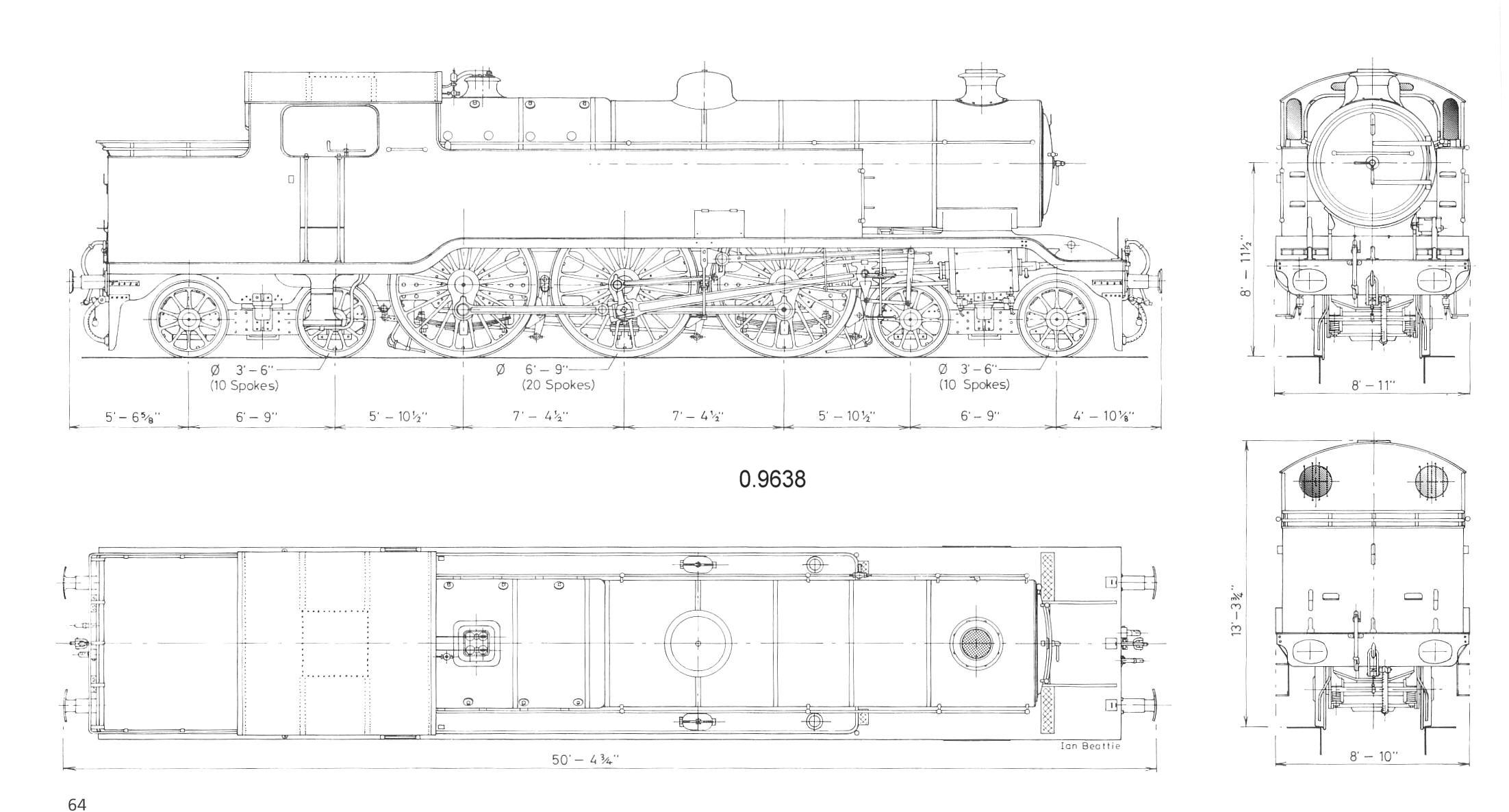
  • Wheel diameters are already given on the plan 3'6" (1.07m) and 6'9" (2.06m)
  • The bogie wheels are 3'4.5" (1.03m) either side of the bogie swivel points.
  • The front bogie is 537 pixels (5.175m) in front of the pivot centre
  • The rear bogie is 517 pixels (4.982m) behind the pivot centre
  • Bogie tops are about 0.69m above the rail
  • The wheel rim width is about 12cm
  • The driving wheels, starting from the front, are at the following positions relative to the pivot: +2.37, +0.11, -2.17
  • The footplate (ignoring where it goes up over the drivers) is 1.35m above the rail top and it is about 14.32m long (ignoring the buffers)
  • The driver con rod is 0.35m from the wheel centre (for outside cylinders, the offset is half the cylinder stroke measurement)
  • Spokes look to be about 0.06 wide at the base and tapered slightly (I'll ignore this for the bogies)
front bogie pivot from axis 	5.175m
front bogie height 		0.69m
front Bogie wheel radius 	0.535m
front bogie 2 axles spacing 	1.03 and -1.03
front Bogie wheel no of spokes 	10
front Bogie wheel spoke width 	0.06m
front Bogie wheel rim width 	0.12m
-------------------
footplate height 		1.35m (ignoring where it goes up over the drivers for the moment)
footplate length 		14.32m
No of axles 			3
Drivers - 3 axles at 		+2.37, +0.11, -2.17 relative to the pivot point
Driving wheel radius 		1.03m
no of spokes 			20
spoke width 			0.06m (at base, and taper slightly)
rim width 			0.12m
conrod offset 			0.35m (for outside cylinders, the offset is half the cylinder stroke measurement)
-------------------
rear bogie from axis 		-4.982m
rear bogie height 		0.69m
rear Bogie wheel radius 	0.535m
rear bogie 2 axles spacing 	1.03 and -1.03
rear Bogie wheel no of spokes 	10
rear Bogie wheel spoke width 	0.06m
rear Bogie wheel rim width 	0.12m

Phew - finally we start up 3D Canvas!

Select the MSTS Engineer plugin from the Plugins menu. The way to use this plugin is to select one of the pre-defined options that is closest to what you are about to build (for us this is the 4-6-2)

Now fill in the numbers...

Bogies  (this page applies to both BOGIE1 and BOGIE2 - the latter has a negative position relative to the Main object)

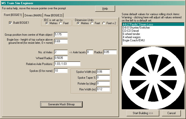
Pressing the "Generate Mask Bitmap" button draws an image of the spoked wheel on the right and copies it onto the windows clipboard - use your paint program to paste in a new image and save this file for later.

Drivers:

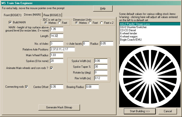
You will notice here the vertical centre spoke - on the plan it shows spokes either side of the centre when the rod is at its lowest position so I need to rotate the wheel by 360/20/2 = 9 degrees this goes in the box under the taper % option.

Now press the Generate Bitmap mask again and save this wheel mask somewhere safe.

Finally, press the "Start Building>>>" button and wait a few seconds.... This has just built 1798 polygons worth of model for you!
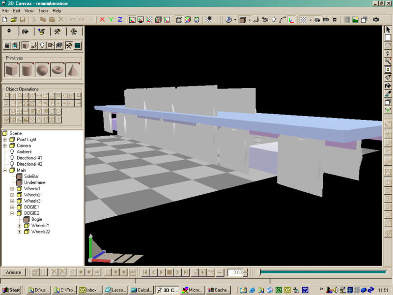
Now save.....

One good thing about MSTS Engineer is that it remembers what you did last time. If your model is not right, start a new Scene and run it again - your previously entered values are still there for correction - just don't select one of the templates or you will lose them.

Probably enough for a first attempt...

Comments/Questions?

Ianm42: "For Paint Shop Pro v7 the measuring can be carried out in a similar manner, using either the selection box tool, crop tool or preset shape drawing tool. However, the required information is only shown while you have the mouse button pressed. As soon as you release the button, the information disappears. In the example shown below, the size of the selection box is 1133x5 (used for calculating the rotation angle needed to square up the drawing)"

mikesimpson: "Thanks for the first lesson - Just a couple of comments, especially as some newcomers will be attempting this model, I am also building Remembrance.

1. I usually model in feet/ins because all my old UK plans are in these measurements, so I have 3D Canvas set up for these sizes. I suspect others may do the same, so perhaps you should have advised users to set their program up in metres first."

(This has since been changed and the Engineer plugin now accepts feet/inches - even when modelling in metres.)

2. Your instructions do not mention making Bogie 2 in Train Sim Engineer, you give the dimensions at the beginning, but the instructions go straight from building Drivers (Main), Generate their Bitmap, then click 'Start Building' - This may confuse some."


Notes on what the MSTS Engineer is and does

  • Plugins (and scripts in the Pro version only) are a "really useful" (tm) feature of 3D canvas.
  • They are DLL's, usually written with visual basic 6, that can build or modify groups, objects, points, faces etc to a scene or manipulate objects in a scene.
  • The Engineer plugin was designed to give a quick start to building various types of rolling stock. It generates a group hierarchy and objects appropriate for exporting to MSTS.
  • The wheels it generates are an attempt to make polygon efficient, solid looking, spoked wheels with a flange in around 120 polygons. In order to do this, there are a few compromises (e.g. the flanges are flat and spokes are rectangular in section) but the end result is a reasonably happy medium between a fully modelled wheel (which usually end up at over 350 polys each wheel) and the default flat Scotsman wheel.
  • On the main driving wheel objects - looking from the rear to the front, the wheels on the right side are the "master" wheels. The con-rods on the right are assumed to be in the lowest position - you can see this when examining the generated model.
  • Take time to look at the hierarchy generated - the con rods on both sides are attached to the rear driving wheel on the right, with the pivot point on the bearing where it attaches to the wheel.
  • The left wheel is also attached to the right, as a child group called "wheel", and rotated 90 degrees (for quartering)
  • This is all done to give smooth animations, by rotating the con-rods in the reverse direction to the wheel rotation.
  • In order to restrict the number of dimensions you need to enter, it makes a few assumptions. Firstly, the wheel sets are standard gauge 4' 8.5". Also the Solebar object is centred over the pivot point and is given a default width and height - this is for you to adjust after the plugin has run (similarly with the bogie boxes) - In fact for Remembrance we shall probably be replacing the solebar object.

  • There are options at the top that you need to set depending on whether you are working in feet or metres. At all numeric prompts in the MSTS Engineer plugin you can also enter values as feet/inches e.g. 3'6" or 66" - on moving to the next input, the plugin will convert this value to either metres of decimal feet depending on your settings.

Go To Chapter 2