A Steam Loco for MSTS Using 3DCanvas
by Paul "decapod" Gausden

Chapter 8 - Detailing

Sorry, this one is a bit of a rush job as I've got to get it finished off soon. Most of the operations should be second nature by now anyway :)


Buffers

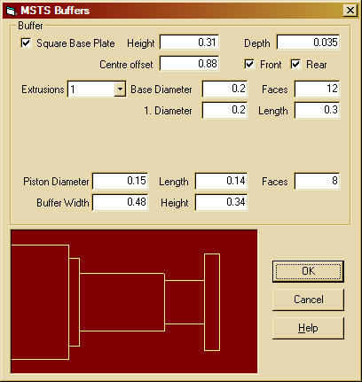
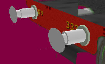
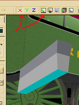
Trust me to write a Buffer building plugin that does not work for this model - the buffer beam attachment points were round on Remembrance. However, it's all good practice...

  1. Select the buffer beam object - conveniently still separate from the footplate object.
     
  2. Run the buffer beam plugin and enter the values from the plan...
     
  3. Delete all the base objects.
     
  4. Build a 12 sided cylinder, scale to the correct size and shift into position by one of the buffers.
     
  5. If you make this new group a child group of the buffer group, you can enter the offset value for the X position (-0.88 for the front left buffer) and the Z position half of the buffer beam length (plus half the cylinder thickness) then just adjust in the Y plane to make central.
     
  6. Delete the hidden back faces and any downward pointing faces and optimise each cylinder.
     
  7. Try building and positioning just one, then copy and paste it back onto itself to create a child cylinder. The just set the positions to x=1.76, y=0, z=0 to position the right front buffer correctly.

  8. You can use a similar method to position the rear cylinder objects by adding a 180 degree rotation and entering the negative value of the length of the beam object for the z coordinate.
     
  9. Finally, once all is correct, drag these objects into the buffer group itself.


Couplings And Pipes

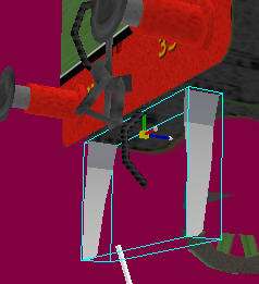
Here I make use of objects stored in my library. I recently added the hooked screw coupling and an updated vaccuum pipe. Library objects save a huge amount of time - once you have a reasonably generic part you like, compress its layers and add it to the library for future use.

  1. For the hooks, drag the hook object out of the library and onto the footplate object, to create the rear facing hook.
     
  2. This should create a child group in main - set the properties to X=0, y=1.2, z= -half the footplate length (about -7.4).
     
  3. 3) Then with the X axis restricted (Red X button on the menu down) adjust the position of the rear hook to the correct height.
     
  4. Repeat for the front hook, but add a Y axis rotation of 180 degrees to the group properties. (Delete any hidden faces) Use a similar technique of positioning, to add the screw couplings and pipes front and rear.

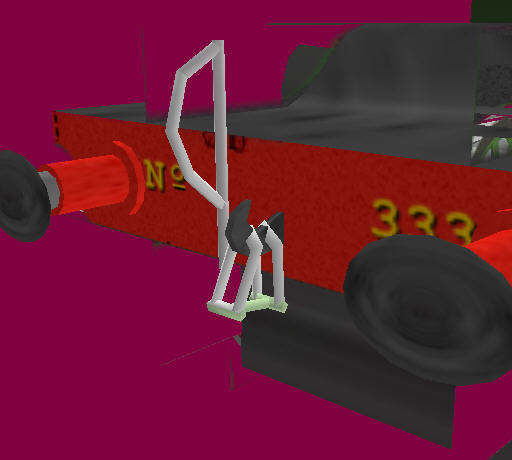
    The lower pipe (steam heat?) was created by adding another vacc pipe from the library and removing a few of the faces. All these extra part object were then dragged into the "bits" group that contains all small objects on or below the footplate. They were also painted, using the fill tool, from areas of the same texture as the rest of the objects in that group.


Finishing Off Below - Brakes

Due to lack of time, I'm probably going to rush through adding the last few details below the footplate (and miss off a couple completely).

  1. Create a cube and resize to x=1.51, y=0.85, z=0.38, then remove all but the two end faces.
  2. Copy and paste this into the main group and position them in front of the driving wheels as per the brake shoe positions on the plan.
  3. Fill with the brake shoe texture using the default fill mode (does both sides at once)
  4. Finally drag these objects into the "bits" group with all the other small parts.


Finishing Off Below - Track Clearers

  1. Start with a cube the same width as the inside frames (1.4m), with Y and Z sizes set to about 17cm (vertical part below the frames);
     
  2. Extrude the lower face by 0.22m;
     
  3. When looking from the side, with default edit mode and the X axis restricted, use the Edit control on the lower left to adjust the width of the lower face to 1.51m.

  4. Extrude the lower face again by 0.38m
     
  5. Adjust the horizontal edges on the front face with the Z axis restricted (if you are building the rear clearer first) to make the shape taper slightly towards the bottom.
     
  6. Chamfer the lower edge

  7. Finally delete all faces except the ends and run the "double side" plugin on the whole object.
     
  8. Drag the group into the main group, position correctly.

    >/li>
  9. Copy, paste, position and rotate Y by 180 to add the one at the opposite end.
     
  10. Finally drag these objects into the "bits" group and texture as before (with a section from the frames so they look similar)


Finishing Off Below - Steps on front of footplate

  1. Build from two resized cubes, positioned on the main object and added to the bits group.
     
  2. Selecting and deleting the front lower edge (and all hidden faces) gives a triangular lower support. The lowest point then needs a small adjustment with the mouse to stop it appearing too far below the foot plate.
     
  3. Texturing was done via the fill tool on each object, using the screen coordinates mode, when viewed from square above (like the cab roof)


Finishing Off Below - Front of frames above the footplate

  1. These were built using the extrude tool again (using a small section chopped out of the plan as a backdrop)

  2. The object was rotated with the shift object operation to the correct orientation and rescaled to the plan size, the width (X) dimension set to 0.03 (about 1").
     
  3. Faces that are likely to be hidden were removed and the object optimised and centred with the Centre Object Operation.
     
  4. 4) The object was then made a child of the main group and positioned (which highlighted a slight discrepancy in my footplate size, so I had to resize the object vertically with the edit control)
     
  5. Once in position, the object was copied and pasted back onto itself and positioned so that X was the frame width and Y,Z were both 0.0, making the two objects exactly the same position across the footplate.
     
  6. Both objects were then dragged into the "bits" group and filled with part of the frame texture. I have been trying hard to remove as many hidden faces as possible, the model so far stands at just over 4100 polys which I think is not bad for the size and detail we have so far.
     

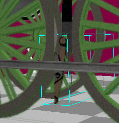
Not much more to do now. I'll probably just do the smoke box and bogie details and call it a day. If you've got this far, then any extra detailing is up to you.

Go To Chapter 9