A Steam Loco for MSTS Using 3DCanvas
by Paul "decapod" Gausden

Chapter 2A - Round Wheels

I imagine you are all eager to get this beast running?

These days I hardly ever put the model into MSTS before it is finished, but this time round I will at least get something going by the next lesson (I hope).

I am also going to build everything below the footplate level first, so it will not look like a steam engine until quite late on. I have my reasons for this which may be apparent later.

One thing I forgot to mention in Lesson 1 - also make sure you have photos of your subject, plans are not always easy to interpret and often miss some detail.

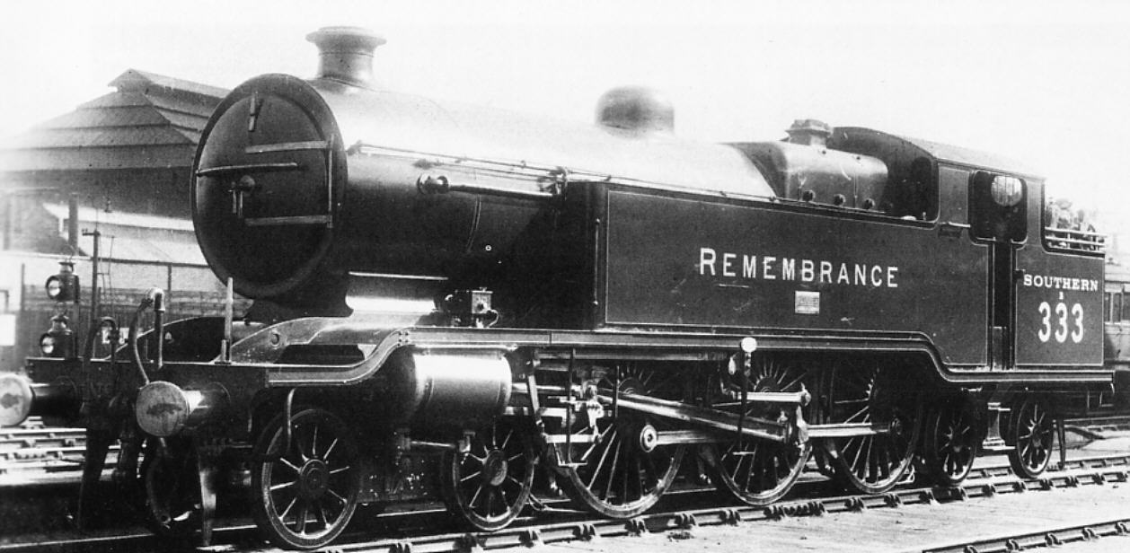
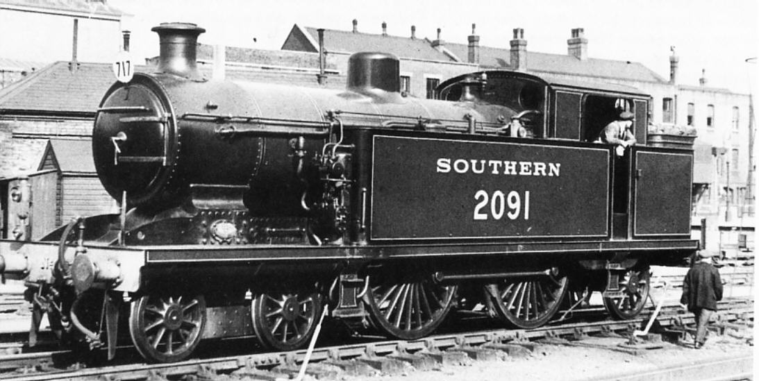
Here is the 4-6-4 and Ian's I3 4-4-2 dressed in Southern Railways livery - probably in Urie Sage Green from early 1920's, black edging with white trim lines. (Haresnape, Railway Liveries 1922-47)


On with the modelling... or should I say texturing

What we have doesn't look like it will run very well on rails, what with it's square wheels. Also if we want to try and get something running quickly, every part on our new model must have a texture assigned to it.

Going back to our two wheel masks bitmaps we saved earlier, load these into your paint program.

As a rule of thumb, I generally use 256x256 masks for wheels of 4' and over and 128x128 for smaller (or sometimes 192x192) - again, sticking to these sizes is important for texturing as it allows us to accurately map onto the wheel so it doesn't appear to wobble.

  1. To the main driving wheel mask, I first add the connection point for the con rod onto the driver mask - on the plan this is 30 pixels down and about 35 pixels wide - the wheel on the plan is 218 wide, so on the texture I need to paint a white circle 35/256*218 = 43 pixels wide and 30*256/218 = 35 pixels below the centre - then fill in the appropriate areas where it joins the hub.
  2. What I do next is create a blank 512x512 TGA file (which will become our ACE file later).
  3. copy the driving wheel mask and paste it into the _mask_ channel of the new TGA, positioned in the top left (so it takes up the top left quarter of the image)
  4. resize the bogie mask to 128x128, and attempt to clean up any grey areas that appear by filling with white or black for light grey or dark grey areas (PP7 uses magic fill tool set to a 50% range, then click on white area, switch to black and click on black areas) - also make sure the hub centre is about the right diameter in relation to the plan.
  5. copy and paste the bogie mask onto the TGA file mask channel and position it at x=256, y=0 - next to the driving wheel but not overlapping.
  6. finally, on the colour area of the TGA, colour in the wheel and add some detail - To get a nice "aliased" effect, I drew the hub rings with a slightly feathered paintbrush, starting with the largest in the dark colour, then one slightly smaller (2 pixels smaller) in the flat green - and so on till the middle dot.

Accuracy is important for this job otherwise the rings will wobble when running - remember the paint program works from the top left corner, usually x=0 and y=0, so the centre of the driving wheel is at x=127 y=127.

Next to the bogie wheel, I added a few small squares of black/brown splodges, grey and a brown edge which get used to cover large amounts of the model.

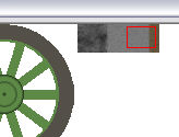
I "cut out" the buffer beam shape and added it to the texture and finally, borrowed the con rod texture from my Aberdare - which was originally drawn just as a grey box with shading to make it appear 3D (more on that later)

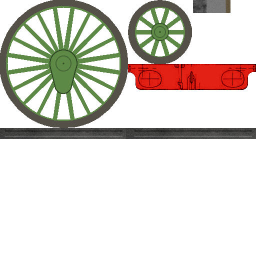
I then saved the texture as LB464W.TGA - here is an idea of what it looks like so far...

Back to the model...

In the control panel on the left, select the Material panel.

On the material Palette, select the second tab (Primary texture) and use the "open" to select the new texture.

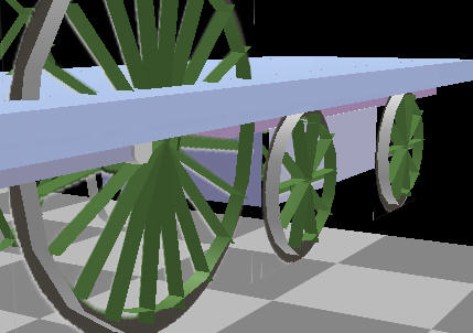
You should now see something like this:

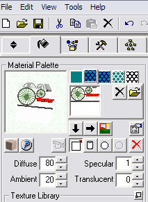
Note the settings for the lighting properties - make sure you read the Train Simulator tutorials in the 3D canvas help about what happens when you change these values. (In practice I rarely change from the values shown here)

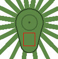
  1. Now press the "crop texture" button (green field with red square on it) - the texture pops up.
  2. Drag the red square around the driving wheel - now to fine tune, enter exact values in the lower 4 fields Origin Left 0.0, Top 0.0, Width 0.5 Height 0.5 - These are what is known as UV values, basically a fraction of the width and height of the texture. Because we have been exact with the wheel size, we can specify exact values. Press OK.
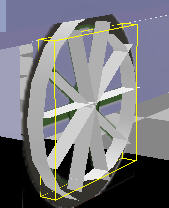
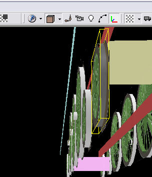
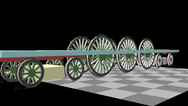
  3. Now set the Orientation selection on the top menu (see lesson zero) to "Edit using face coordinates" and look at the driving wheels on the right side (from slightly below)
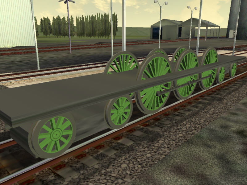
  4. Select the Fill tool on the right menu bar and click on the "faces" and "flange" objects for the 3 drivers on both sides.

For the Bogie wheels, do the same - just adjust the texture coordinates to 0.5,0.0,0.25,0.25 and use the fill tool straight away on all flat faces.

I'll stop for the moment to make sure everyone no one has problems...

I have also posted a small object library on the Highworth site, along with a couple of other plugin updates (not needed till later). If others would like to contribute library parts, it may be worthwhile zipping them up and sending them to me so I can put them all in one library.

The plugin did accept feet/inches in the inputs before, but they weren't reliable. Now you can work reliably (? I hope) even mix feet/metres in the inputs: by entering 3'4.5" (or 40.5") for the main wheel diameter it will directly convert it to metres or decimal feet depending on how you have set up the program.

It's worth adding that the basics of creating texture files and alpha channels using Paint Shop Pro v7 are covered in chapter 1 of Ian MacMillan;s '4 wheel wagon' tutorial available from http://www.amabilis.com

.


Chapter 2B - Round Wheels Turning

Next we need to texture the spokes and inner rim - not so easy, the wheel face is in the way.

  1. Right click on all the wheel faces (including bogies) and uncheck the Visible option on the object menu.

  2. Use the crop texture window again (from the material palette tab) to select a small area of the colour you need for the inner rim and spokes - I usually pick the area under the con rod bearing.

  3. Select the fill tool (edit orientation not important this time - I usually set back to default) and click on each spoke and inner rim object for all the wheels. Remember - if you miss the object you were aiming for, the "Undo" button on the main toolbar will return the original texture.

  4. Select the hierarchy tab on the left and right click on all "Faces" (V1.2 engineer plugin) or "FrontFace" (previous version) objects and check the Visible menu option again so the wheel faces re-appear.

    Alternatively if you're feeling lazy, save the file and open it again...

To paint the outer rim, I usually like to put a small band of brown near the flange to make the transition from the grey a bit more smooth.

To achieve this:

  1. Use the crop texture window to select a small square with a bit of brown down the right side.

  2. make sure the Orientation mode is "Edit with default"
  3. look at the model from below and from one end, then fill all the rim objects on the left hand side.

  4. now rotate your view point to the same position at the other end of the model and do the same again (the right hand wheels last time should now be on the left!)

OK - let's fill in the remaining objects temporarily...

  1. crop the texture to the connecting rod texture and use the fill tool on the rod by viewing the model from square on each side.

    Incidentally - have you noticed the con rods are only a top face and a side face? They look a bit odd from below, but in theory the MSTS viewpoint is unlikely to be able to see this.

  2. crop a small grey or black area texture
  3. fill the footplate/solebar, bogies, bearings and frames objects from any angle.

MSTS Export

First create a new folder in your trainset (I'll be using LBSCR464T)

You could try using the "Train Simulator Wizard" in the 3DC plugins menu to do a simple export - If you do, skip over the "engine attributes" options (leave as zero) as this can disrupt the wheel and rod animations already generated. No need to select the bogies either. I mainly use this plugin to generate the size information for a custom ENG file and the SD file.

I also ignore the create animation, sounds and cabview options on the last page, and try to use optimized distance levels (can take 3-4 mins to run this) and textures.

If you use this you can skip to the last couple of paragraphs...

Being an "old hand", I just copy an existing aliased cabview folder and an ENG and SD file from a 'similar' loco (from my Aberdare to start with in this case) - then make adjustments with the wordpad editor so that they reference the LBSCR464T.S file I will be creating soon.

Make sure the ENG file has the correct loco name so you can spot it in the game list - don't bother changing the effects or sizes/positions for this test.

Now use MAKEACEWIN.EXE in your MSTS Utils folder and browse for the wheel texture (LB464W.TGA) and convert this to an ACE file in the LBSCR464T folder with the same name as the TGA i.e. LB464W.ACE

When creating ACE files, I almost always use DXT compression. This tends to produce smaller files that run more efficiently than any other format. You may lose some quality, but it isn't noticeable, and in some cases as we will see later, actually improves the look.

The only down side is that you cannot use them for translucency (dirty windows), only complete transparency.

Finally we need the S file.

Within 3D Canvas, right click on one of the objects in the Main group (currently only underframe or solebar) and select the Export/To Microsoft Train Simulator options.

Browse to the trainset folder, enter the S file name and press OK.

There is another prompt to say do you want distance levels - say Yes (you should always say yes here, except for extremely simple scenery objects with no groups)

Yet another prompt says do you want optimized distance levels - try either Yes or No here (Yes may take a few minutes to run the export)

When this has finished you should be able to create a consist for the loco and select it to explore a route.

If you exported the optimised distance levels of detail, take a look at the poly count with the Shape File Manager or the right click counter option - this would make a frame rate friendly AI loco.

Sounds great aliased to the Goldsdorf 380 sounds.

Additional Notes

The Trains Sim Wizard can completely screw up the MSTS Engineer work - do not overwrite the animation or identify the parts.

For extra reading on texturing and orientation modes - read the Oriented Modelling tutorial in the 3DC help file.

Finally - if you do see flashing wheels when running the model... (unusually mine do not - more normally they do flash), select the offending part, click on the Crease Operation (small inverted V button) then just press OK without changing anything) - do this for all wheels. Now export the S file again.

One more thing on the Engineer... I think the wheels are a bit thin, it uses 0.1m (about 4") as the tyre width, but some we saw at Didcot were 6"-8" thick - should I change it or does it look OK? (Version 1.3 of MSTS Engineer changed the width to 0.12m - 5")

I find the easiest way to texture the spokes and rims is to select a bit of colour, as you did, then select each spoke or rim object in the hierarchy panel in turn, then use the texture fill tool in the panel above that. No need to make faces invisible, etc.

Then I go through the hierarchy again, selecting each bit of the wheels in turn, and apply the crease to everything, just to be on the safe side. It's a bit tedious though.

Finally, I run the model through Train Sim Wizard once (usually when I have the buffers in place so the maximum dimensions have been reached) and it sets up all the files for me to then tinker with. After that, I export further versions manually.

The creasing really only needs to be done on flat objects (faces & flanges) - the plugin should calculate the rest of the normal vectors (which is the cause of the flashing) correctly.

I'll probably use the wizard near the end to build a correct SD and use the dimensions and steam effects locations from the ENG file - as you say, after that you really only need to update the S file and/or textures after you have done this once.

I should add one word of warning about selecting objects in the hierarchy, always count to two before moving the mouse as sometimes, if you move before 3DC has readjusted itself, it decides to move the selected item into some random location in the hierarchy. One of 3DCs little featurettes. 

If you can faintly see the square shapes (just a dotted line with a few pixels in them) in MSTS, then either the UV mapping is not exactly 0.0,0.0,0.500,0.500 or the wheel mask is not 256x256 - you can check the coordinates by selecting one wheel face and running the UVRemap Operation (red grid)

With the 3DC texture cropping, beware that there are 4 decimal places, but ony 2 are shown - you can use the right arrow key to see if there are more.

Go To Chapter 3