A Steam Loco for MSTS Using 3DCanvas
by Paul "decapod" Gausden

Chapter 9 - Yet More Details

It is starting to get to the stage where adding the detail objects is becoming repetitive:
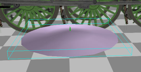
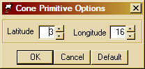
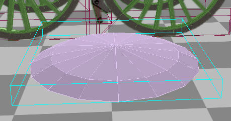
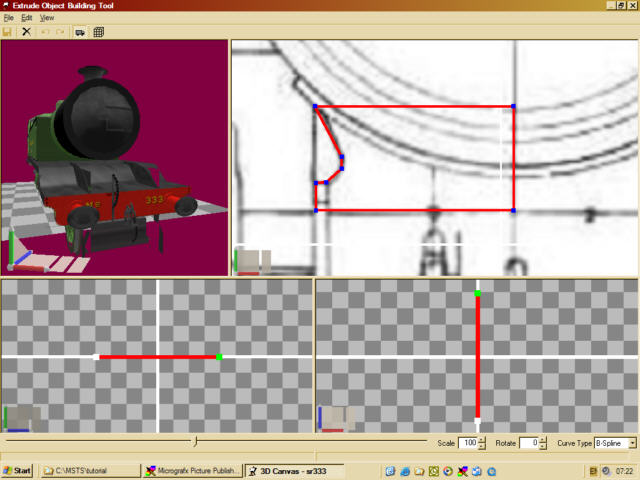
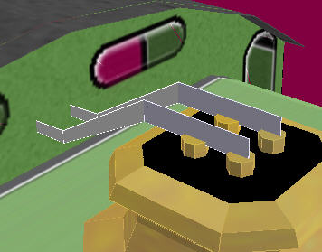
  • Build the object
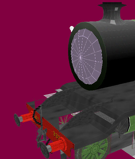
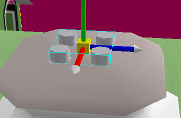
  • drag the group to a parent for relative positioning
  • when correct drag the object into its final group
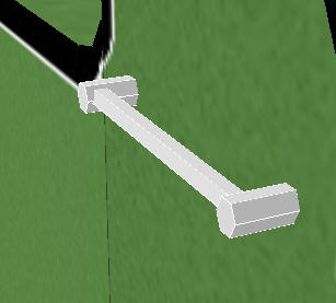
  • remove faces and optimise
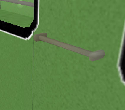
  • texture The only bits that change seem to be the build object part.

There are not many more techniques I make use of to build pieces. In general, if it is simple to build, then it is likely to be relatively efficient. I will describe a few more, but may leave out a few simple pieces I have already added.


Smoke Box Door

These can be relatively high poly count items for something that doesn't show up much. Mainly because of the curves involved. I usually (these days) build mine from a cone primitive.

  1. scale the cone so the base is the same size as the door and the height is about 1.5 times the depth you need for the final door.

  2. change the cone latitude to 3 on the Open/Source right click menu for the cone.

  3. Right click drag the centrepoint down until the object is the required height.

  4. Cut and paste the cone into the boiler group and rotate it 90 degrees around the x-axis. Then position the group correctly at the front of the Boiler.

  5. remember to remove the back face and drag the door object into the boiler group.
     
  6. add the texture.


Smoke Box Base

This object needs to be built using an extrude object in 3DC.

  1. Use the extrude object tool as before. This time, as the object is symmetrical I will only be building half of it. The centre line must be absolutely vertical (same X coordinate for points).

  2. Once the object is built, scale it to the correct size and shift rotate it to the correct orientation.
     
  3. Tun the Mirror object operation on the object, mirroring along the Z-axis (when using world coordinates). This may take a couple of goes as you may have to flip the object first if the mirror happens on the wrong side of the object.
     
  4. Finally check the size is OK, drag the new object group into the boiler group and position correctly. Then once you are happy with this, drag the extrude object into the boiler group itself.


Safety Valve Covers - (similar to funnel and dome)

  1. Starting with a cube scaled to 0.4 x 0.05 x 0.4, chamfer the four small vertical edges (with a small shift adjustment afterwards) to get an approximate shape to build from.

  2. Select the lower face and use the flare extrude plugin (parameters 0.12, 0.12, 2, 1) for the lower curve (now remove the lower face as it is hidden).
     
  3. Select the upper face and use the flare extrude plugin (parameters 0.05, 0.05, 2, 1) for the first upper curve.
     
  4. Select the upper face and use the flare extrude plugin (parameters 0.05, -0.08, 2, 1) for the second upper curve.

  5. Position this object in the boiler group.
     
  6. Scale a 7 or 8 sided cylinder to about 0.06 x 0.04 x 0.06 and remove the lower face.
     
  7. Copy and paste this object back onto itself 3 times (to create 3 child groups)
     
  8. For thest child groups, by changing either the x or z coordinates or both coordinates to about 0.09 and the rest to 0.0 you can arrange the objects into a square.
     
  9. I then merged all the objects into a single object and centred the object, then positioned it as a child of the SV cover.

  10. The cover and valves were then dragged into the boiler group and textured (poetic licence brass colour - was probably green) The valve levers were build from a cube with all but the left and right faces removed (an operation that happens many times when building locos).
     
  11. This cube is scaled to 0.000001, 0.05, 0.3 (or thereabouts) and optimised - this effectively welds the two faces of the flat object back to back, reducing the number of points.
     
  12. The rear *edge* of this object can now be extruded by 0.3, right mouse dragged down slightly and the edge shrunk slightly by dragging over the Y panel of the edit control.
     
  13. The rear edge is then extruded again by 0.15 and this time needs shifting up slightly. Make sure the faces on both sides of the object have been extended.

  14. Copy and paste the object onto itself and set the new group X coordinate to the appropriate width (width of valve tops), Y and Z are zero.
     
  15. Merge the two objects and position on the model (in the same group as the boiler).

Hint 1 - the Centre object operation helps make the positioning easier (X coordinate relative to the boiler should be 0.0)

Hint 2 - When chosing a group to put an object into, make sure the texture used is the same as all other objects in a group.

After 30+ groups and about 150 objects, I am still able to export this model with the optimised 6 LOD's because of this.


Handrails

These are made from 5 sided cylinders with the ends removed.

Hint - shift rotate and scale the 16 sided cylinder first before changing the number of faces. Also a good idea to use the centre object operation after you have changed the number of faces. The fixing points are made from 6 sided cylinders (slightly larger diameter than the rail) with one end removed. The fixings are made a child group of the bar and positioned (for a horizontal rail) with X and Y as 0.0 and with Z at one end. The fixing is then shifted so the bar is near the top, but the fixing centre has not moved. You can now copy and paste this fixing as many times as needed onto the handrail object and position exactly with the Z coordinate. I usually merge all the fixings and rail into a single object before positioning the handrail on the model.

Now this doesn't look particularly round! You need to run the Crease operation and drag the slider down till the viewport shows a smooth object. Beware - if you do some more operations on this rail, the smoothing may be lost. Make sure you do a final check before exporting. Canvas 6 has a crease level defined for each object (which you must set) which retains smoothing through operations.


Bits

Here is a small pic of a few other bits I've added - the steps are just squashed cubes with *all* hidden faces removed - the ones on the tank ends only have 3 faces.

The handrails were made using the technique as above - it is quite long winded, I'll definitely be doing a plugin to generate these at some point soon. (I had also forgotten to chamfer the front two vertical edges of the tank in the earlier parts) I have also been running her in the sim, taking a close look at the details and tweaking the texture mappings etc. Getting it looking right is definitely the most time consuming task. Here she is looking very shiny - the SFM is the simplest option to do this with, Canvas can be a bit fiddly to get right. Once again, group organisation and naming is the key to success here.